Design Guide | iC7 Series Liquid-cooled System Modules
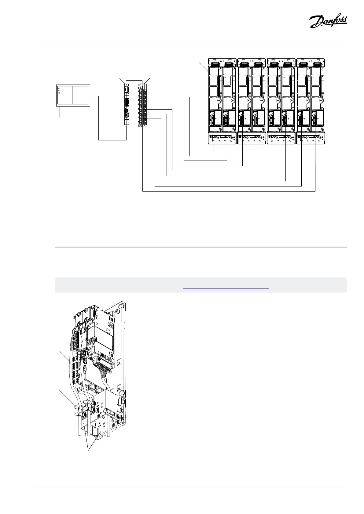
Figure 109: Connecting the Fieldbus Cable and the Fiber Cables
1 PLC (not included in the delivery) 2 Fieldbus cable
3 Control board 4 Star coupler board
5 Fiber cables 6 Power units
8.15 Installing the Control Cables into the Control Terminals
1. Install the control cables into the control terminals.
See the pin numbering of the I/O and Relay Option in 8.8 I/O and Relay Option Connections.
Figure 110: Example of Installing the Control Cables
Danfoss Drives Oy © 2024.03 AJ475942178716en-000101 / 172K2848A | 111
 Loading...


