Design Guide | iC7 Series Liquid-cooled System Modules
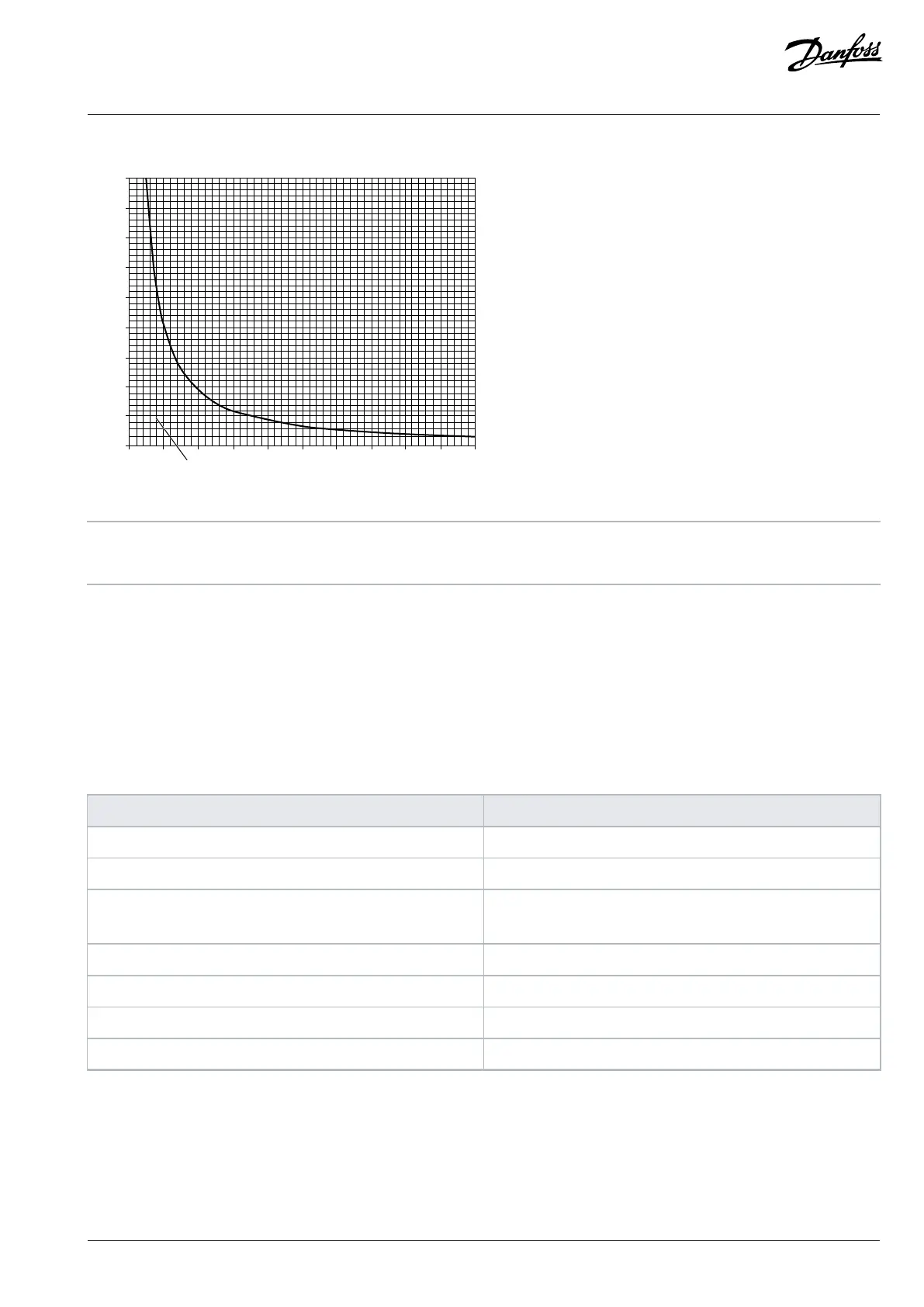
12000
10000
8000
6000
4000
2000
Figure 104: Allowed Load Resistance of Analog Output in Current Mode
A Load resistance B Allowed load resistance
C Output current
8.9.3 Digital Inputs
The I/O and Relay Option has 6 digital inputs. By default, the digital inputs are not isolated, because there is an external wire between the
connector pins 19 (D
GND
) and 23 (GND). The digital inputs can be functionally isolated from the PCB ground of the I/O and Relay Option
by removing the wire. The digital inputs are polarity free.
Digital inputs are overvoltage protected.
Table 36: Digital Inputs Logic Levels and Other Requirements
Parameter Value
Recommended Operation Voltage 0...24 V +20%/-10%
Overvoltage Limit 33 V
Logic Level 0 = V
TL
≤ 5 V
1 = V
TH
≥ 15 V
Input Load 7.5 mA constant current and 10 kΩ resistive load
Reaction Time < 5 µs
Maximum Frequency 100 kHz
Electrical fast transient (EFT) 2 kV
8.9.4 Digital Outputs
The I/O and Relay Option has 2 digital outputs. The digital outputs are the push-pull type. The digital outputs can also be used as the
open collector type.
The digital outputs are short-circuit protected.
Danfoss Drives Oy © 2024.03 AJ475942178716en-000101 / 172K2848A | 105
 Loading...


