EasyManuals Logo
Home>Danfoss>Media Converter>iC7 Series

Danfoss iC7 Series Design Guide

Danfoss iC7 Series
224 pages
To Next Page IconTo Next Page
To Previous Page IconTo Previous Page
Page #83 background imageLoading...
Page #83 background image
Design Guide | iC7 Series Liquid-cooled System Modules
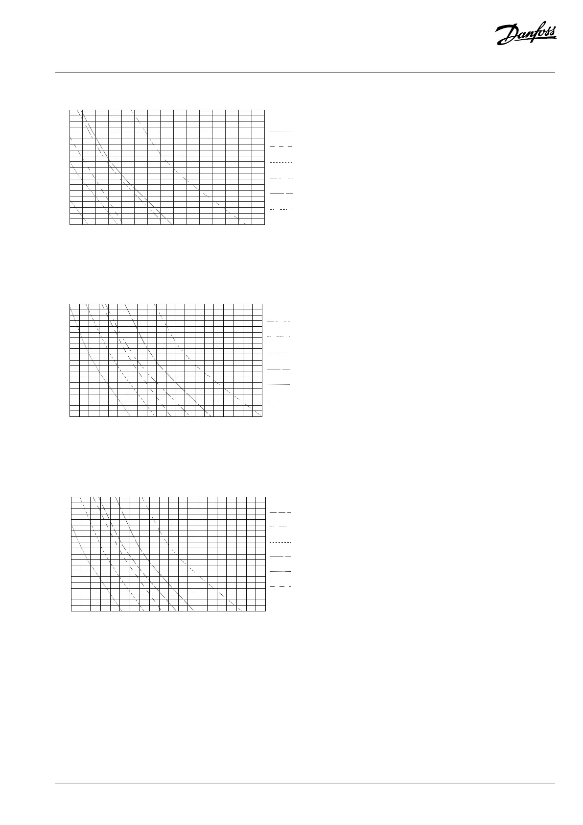
f
sw
[kHz]
l [m]
C [nF]
4.0
3.5
3.0
2.5
2.0
0
50 100 150
0
75 150 225
1250 VDC
Mod. 1
1250 VDC
Mod. 2
1122 VDC
Mod. 1
1122 VDC
Mod. 2
1025 VDC
Mod. 1
1025 VDC
Mod. 2
e30bi110.1 0
Figure 82: Safe Operation Area: 416 A dU/dt Filter, Low Output Frequency Range
f
sw
[kHz]
4.0
3.5
3.0
2.5
2.0
C [nF]
0
150
300 450 600
l [m]
0
50 100 150 200
1025 VDC
Mod. 1
1025 VDC
Mod. 2
1122 VDC
Mod. 1
1122 VDC
Mod. 2
1250 VDC
Mod. 1
1250 VDC
Mod. 2
e30bi113.1 0
Figure 83: Safe Operation Area: 820 A dU/dt Filter
f
sw
[kHz]
4.0
3.5
3.0
2.5
2.0
C [nF]
0 150 300 450 600
l [m]0
50
100 150 200
1025 VDC
Mod. 1
1025 VDC
Mod. 2
1122 VDC
Mod. 1
1122 VDC
Mod. 2
1250 VDC
Mod. 1
1250 VDC
Mod. 2
e30bi114.1 0
Figure 84: Safe Operation Area: 820 A dU/dt Filter, Low Output Frequency Range
7.13.2 Common-mode Filter
With the Common-mode Filter, the nominal switching frequency is 2 kHz. The maximum switching frequency is 4 kHz.
The Common-mode Filter can operate in the whole output frequency range of the drive.
Danfoss Drives Oy © 2024.03 AJ475942178716en-000101 / 172K2848A | 83

Table of Contents

Other manuals for Danfoss iC7 Series

Questions and Answers:

Question and Answer IconNeed help?

Do you have a question about the Danfoss iC7 Series and is the answer not in the manual?

Danfoss iC7 Series Specifications

General IconGeneral
BrandDanfoss
ModeliC7 Series
CategoryMedia Converter
LanguageEnglish

Related product manuals