Design Guide | iC7 Series Liquid-cooled System Modules
7.7 Field Cabling Installation
The field cabling terminals are not included in the delivery of the system module. Install field cabling to the appropriate terminals.
Connect the terminals of the AFE/GC to the LCL Filter terminals with internal cables or busbars. Define the size of the internal cables or
busbars according to the nominal current of the drive, and according to local regulations.
7.8 Installation of Cables with the Power Terminal Adapter
Typically, the motor cables in marine installations have a smaller cross-section compared to the cables in industrial installations, a
maximum of 95 mm
2
. That is why more cables must be connected in parallel. If local regulations require the use of several thin parallel
motor cables, a power terminal adapter (+AFMC) is available for the installation.
See cable selection requirements in 10.4.7 Marine Cable Sizes for INU Modules 525–690 V AC.
7.9 Installing the DC Fuses to the DC Terminals
Use these instructions to install the DC fuses. The DC fuses are available as option +AKFX or +AKFF.
1. Attach busbars to the DC fuses. Make sure that the visual indicator (the red dot) of the DC fuse is facing forward.
a. Screw the stud on the fuse. Make sure that the stud is inserted as far as it goes. The maximum tightening torque is 15 Nm
(133 in-lb).
b. Place the busbar on the stud.
c. Mount the busbar with an M12 nut and washers, and tighten to torque 45 Nm (398 in-lb).
NOTICE
If the busbars on the DC fuses are not aligned, they can strain the fuse structure and break it over time. When tightening the
screws, make sure that the busbars stay aligned.
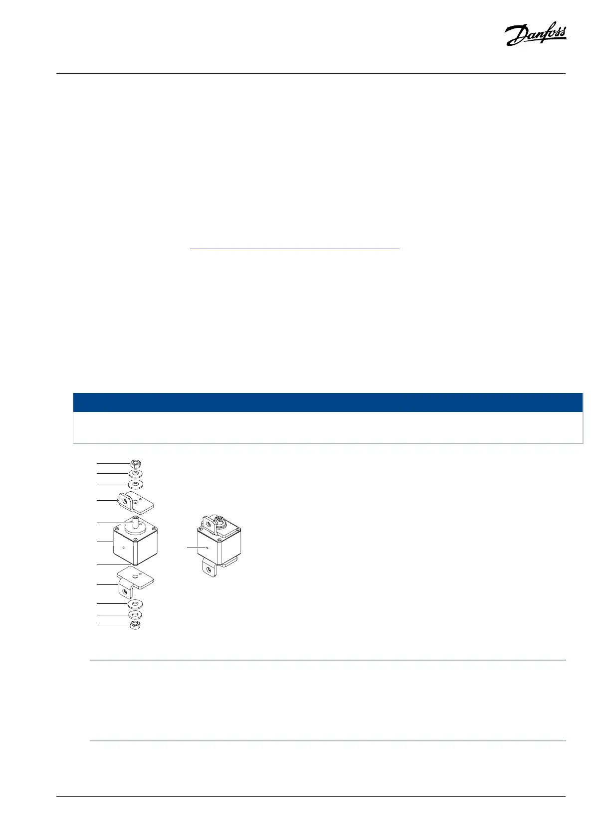
Figure 65: Installing Busbars to the DC Fuses
1 M12 nut 2 M12 spring washer
3 M12 washer 4 Busbar
5 Stud 6 Fuse
7 Visual indicator
2. Attach DC-terminal busbars to the DC terminals of the system modules.
Danfoss Drives Oy © 2024.03 AJ475942178716en-000101 / 172K2848A | 71
 Loading...


