Home
Danfoss
Media Converter
iC7 Series
Danfoss iC7 Series Design Guide
5
of 1
of 1 rating
224 pages
Give review
Manual
Specs
To Next Page
To Next Page
To Previous Page
To Previous Page
Loading...
Design Guide
| iC7
S
eries
Liquid-cooled
System Modules
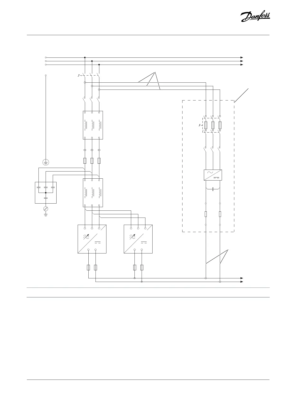
10.3.8
Pr
e
-
charging Circuit
, AR12L
-CA2
-RA1
L1
L2
L3
L1'
L2'
L3'
-RA2
L1
L2
L3
L1'
L2'
L3'
DC-
DC+
L3
L2
L1
-TB3.1
DC-
DC+
L3
L2
L1
-TB3.2
1
2
3
4
5
6
-FC1
PE
1
2
3
4
5
6
-QB1
3
4
5
6
1
2
-QA3
1
2
3
4
5
6
-QB6
L1
L2
L3
PE
3
4
5
6
1
2
-QA6
+
-
-TB6
3
-CA6
1
-PE
1
2
-FC2.1
3
4
1
2
-FC2.2
3
4
L1
L2
L3
-XD6
1
-XD6
2
3
4
-RA6.1
-RA6.2
DC+
DC-
L1
L2
L3
e30bg432.11
A
B
A
A
Double
-insulated cable
B
Pre
-charging circuit
Figure 165:
Pre-charging Circuit Diagram, AR12L
Danfoss Drives
Oy
©
2024.03
AJ475942178716en-000101
/
172K2848A
|
163
162
164
Table of Contents
Contents
3
1 Introduction
11
1.1 Purpose of this Design Guide
11
1.2 Additional Resources
11
1.3 Planning and Design Support Materials
11
1.3.1 Overview of Available Planning and Design Support Materials
11
1.3.2 Locating Support Information
12
1.4 Version History
12
1.5 Abbreviations
12
1.6 Recommended Disposal
13
2 Safety
14
2.1 Safety
14
2.2 Safety Symbols
14
2.3 General Safety Considerations
14
2.4 Target Group and Necessary Qualifications
15
3 Danfoss iC7 Series
16
3.1 Overview of iC7 Series
16
4 Overview of the iC7 Series Liquid-cooled System Modules
17
4.1 System Modules
17
4.2 Control System of the System Modules
19
4.3 Contents of the Delivery
20
4.4 Description of the Frame Designation
20
4.5 Weights
20
4.6 Common DC Bus Drive System
21
4.7 Description of the Model Code
22
4.8 Labels on the Products
23
4.8.1 Labels on the System Module
23
4.8.2 Labels on other Components
24
4.8.3 Product Label
25
4.9 Lifting the Product
26
4.9.1 Lifting the System Modules
26
4.9.2 Lifting the System Modules with Integration Unit
26
4.9.3 Lifting the Filters
27
5 Mechanical Installation Considerations
28
5.1 Storing the System Module
28
5.2 Requirements for the Cabinet
28
5.3 Mechanical Installation
28
5.3.1 Installation Requirements
28
5.3.2 Installation Directions
28
5.3.3 Installing System Modules
28
5.3.3.1 Installing System Modules into a Cabinet Vertically
28
5.3.3.2 Installing System Modules into a Cabinet Horizontally
30
5.3.3.3 Installing System Modules into a Cabinet on their Backsides
30
5.3.4 Installing System Modules with Integration Units
31
5.3.4.1 Installing System Modules with Integration Units into a Cabinet Vertically
31
5.3.4.2 Installing System Modules with Integration Units into a Cabinet Horizontally
33
5.3.4.3 Installing System Modules with Integration Units into a Cabinet on their Backsides
34
5.3.5 Installing Filters
35
5.3.5.1 Installing L Filter into a Cabinet, 400 A, 1000 A
35
5.3.5.2 Installing L Filter into a Cabinet, 1640 A
35
6 Cooling Requirements
37
6.1 Safety in Liquid-cooling
37
6.2 General Information on Cooling
37
6.3 Coolant
39
6.3.1 Quality Requirements for the Purified Water
39
6.3.2 Purified Water as Coolant
39
6.3.3 Antifreeze Mix as Coolant
39
6.3.4 Temperature of the Coolant
40
6.4 Cooling System
40
6.4.1 Materials
40
6.4.2 Heat Exchanger
41
6.4.3 Flow Rate of the Coolant
41
6.4.3.1 Flow Rates in Parallel Power Units
42
6.4.4 Volume of the Pipe
43
6.4.5 Pressure Drop
44
6.4.5.1 Pressure Drop and Correction Factors
44
6.4.5.2 Pressure Drop of IM10L, IM12L, AM10L, AM12L, DM10L and DM12L
45
6.4.5.3 Pressure Drop of AR10L, IR10L, and Filters
46
6.4.5.4 Pressure Drop of AR12L, IR12L, and Filters
48
6.4.5.5 Pressure Drop of the Grid-side L Filter
50
6.4.5.6 Pressure Drop of DR10L, DR12L, and Filters
51
6.4.6 Cooling Circuit Connectors
52
6.4.6.1 Pipe Ferrules
53
6.4.6.2 Insertion of Pipes into Cooling Circuit Connectors
53
6.4.6.3 Inlet and Outlet Connectors of System Modules
54
6.4.6.4 Inlet and Outlet Connectors of System Modules with Integration Units
55
6.4.6.5 Inlet and Outlet Connectors of the L Filter
56
6.4.7 Cooling Circuit Pipes
56
6.4.7.1 Bending Pipes in the Air
57
6.4.7.2 Bending Pipes with a Bending Jig
58
6.4.8 Filling the Cooling System
59
6.5 Condensation
62
6.6 Air Cooling Requirements
62
7 Electrical Installation
65
7.1 Fuses of the Drive System
65
7.2 Guidelines for DC Connections of System Modules
65
7.3 Grounding Principles
67
7.4 Cable Requirements
67
7.4.1 Cable Requirements
67
7.4.2 Requirements for DC-source Cables of DC/DC Converters
68
7.5 Prerequisites for Cable Installation
68
7.6 Recommended Installation of Motor Cables
70
7.7 Field Cabling Installation
71
7.8 Installation of Cables with the Power Terminal Adapter
71
7.9 Installing the DC Fuses to the DC Terminals
71
7.10 DC-bus Connection Inductance
73
7.11 Auxiliary Power Connection, INU
73
7.11.1 Indicator Light Definitions
74
7.12 Installation in an IT System
75
7.12.1 Changing the EMC Protection Level, AR10L
77
7.12.2 Changing the EMC Protection Level, AR12L
78
7.12.3 Changing the EMC Protection Level, LC Filter, OF7Z1, 380 A
79
7.12.4 Changing the EMC Protection Level, LC Filter, OF7Z1, 760 A
80
7.13 Filters
81
7.13.1 dU/dt Filter
81
7.13.2 Common-mode Filter
83
7.13.3 LC Filter
85
7.13.4 DC Filter
85
7.14 AuxBus Communication
85
7.14.1 Usage of AuxBus
85
7.14.2 AuxBus Cable Requirements
87
7.14.3 AuxBus Grounding Principles
88
7.15 The Pre-charging Unit
88
7.16 Derating
90
7.16.1 Derating of Switching Frequency, INU
90
7.16.2 Derating of Coolant Temperature
90
7.16.3 Derating of Voltage Imbalance, AFE/GC
90
7.16.4 Derating of DC-bus Voltage
91
7.17 Modulator Types
91
8 Control Unit
93
8.1 Modular Control Unit
93
8.2 Control Board
94
8.3 Definitions of the Indicator Lights on the Control Board
95
8.4 Control Board Connections
96
8.5 Star Coupler Board
97
8.6 Definitions of the Indicator Lights on the Star Coupler Board
100
8.7 Star Coupler Board Connections
100
8.8 I/O and Relay Option Connections
101
8.9 I/O and Relay Option Interface
104
8.9.1 Analog Inputs
104
8.9.2 Analog Outputs
104
8.9.3 Digital Inputs
105
8.9.4 Digital Outputs
105
8.9.5 Relay Outputs
106
8.9.6 Analog Reference Voltage Output
107
8.9.7 24 V DC Voltage Output
107
8.9.8 Thermistor Input
107
8.10 Assembling the Control Unit Mounting Plates
107
8.11 Attaching the Control Unit Mounting Plates
108
8.12 Installing the Control Unit
109
8.13 Installing Boards to the Modular Control Unit
109
8.14 Connecting the Fieldbus Cable and the Fiber Cables
110
8.15 Installing the Control Cables into the Control Terminals
111
8.16 Connecting the Control Panel
112
8.17 Fiber Cable Requirements
112
9 Maintenance
113
9.1 Preventive Maintenance Recommendations
113
9.2 Maintenance Log for Cooling System
116
9.3 Using the Product Modified Label
116
9.4 Replacing the RTC Battery
117
9.5 Removing the System Module from the Integration Unit
118
9.6 Installing the System Module in the Integration Unit
121
9.7 Draining the System Modules
123
9.7.1 Draining the System Modules, System Modules with Integration Units, and Filters
123
9.7.2 Draining the Power Units for xR10L and xR12L
124
10 Specifications
126
10.1 Tightening Torques
126
10.2 Dimensions
127
10.2.1 Dimensions of the Inverter Module, IM10L, AFE/GC Module, AM10L, and DC/DC Converter Module, DM10L
127
10.2.2 Dimensions of the Inverter Module, IR10L
128
10.2.3 Dimensions of the Active Front-end Module/Grid Converter, AR10L
129
10.2.4 Dimensions of the DC/DC Converter, DR10L
130
10.2.5 Dimensions of the Inverter Module, IM12L, AFE/GC Module, AM12L, and DC/DC Converter Module, DM12L
131
10.2.6 Dimensions of the Inverter Module, IR12L
132
10.2.7 Dimensions of Active Front-end Module/Grid Converter, AR12L
133
10.2.8 Dimensions of the DC/DC Converter, DR12L
134
10.2.9 Dimensions of the LC filter for AM10L
135
10.2.10 Dimensions of the LC Filter for AM12L
136
10.2.11 Dimensions of the L Filter, 400 A
137
10.2.12 Dimensions of the L Filter, 1000 A
138
10.2.13 Dimensions of the L Filter, 1640 A
139
10.2.14 Dimensions of the dU/dt Filter and the Common-mode Filter for IM10L
140
10.2.15 Dimensions of the dU/dt Filter for IM12L
141
10.2.16 Dimensions of the DC Filter for DM10L
142
10.2.17 Dimensions of the DC Filter for DM12L
143
10.2.18 Dimensions of the Control Unit
144
10.2.19 Dimensions of the Control Unit Mounting Plate
145
10.2.20 Dimensions of the Option Connector
146
10.2.21 Dimensions of the Control Board
147
10.2.22 Dimensions of the I/O and Relay Option
148
10.2.23 Dimensions of an Option Board
149
10.2.24 Dimensions of the Star Coupler Board
150
10.2.25 Dimensions of the Pre-charging Unit, IEC
151
10.2.26 Dimensions of the Pre-charging Unit, UL
152
10.2.27 Dimensions of the DC Fuses, xx10L
153
10.2.28 Dimensions of the DC Fuses, xx12L
153
10.2.29 Dimensions for the Control Panel Flush Mounting Kit
154
10.2.30 Dimensions for the Control Panel Surface Mounting Kit
155
10.3 Wiring Diagrams
156
10.3.1 Wiring Diagram, AFE/GC, AR10L
156
10.3.2 Wiring Diagram, AFE/GC, AR12L
157
10.3.3 Wiring Diagram, INU, IR10L
158
10.3.4 Wiring Diagram, INU, IR12L
159
10.3.5 Wiring Diagram, DC/DC Converter, DR10L
160
10.3.6 Wiring Diagram, DC/DC Converter, DR12L
161
10.3.7 Pre-charging Circuit, AR10L
162
10.3.8 Pre-charging Circuit, AR12L
163
10.3.9 Pre-charging Control Circuit
164
10.3.10 The Pre-charging Function
165
10.3.11 Wiring Diagrams of the +24 V Supply for the Control Unit
166
10.4 Cable Sizes
167
10.4.1 List of Cable Size Information
167
10.4.2 Field Cable Sizes for AFE and GC Modules, 525–690 V AC
167
10.4.3 Internal Cable Sizes for AFE and GC Modules, 525–690 V AC
169
10.4.4 Field Cable Sizes for INU Module, 525–690 V AC
169
10.4.5 Marine Cable Sizes for AFE or GC Modules 525–690 V AC
171
10.4.6 Source Cable Sizes for DC/DC Converter Modules, 640–1100 V DC and 640–1200 V DC
172
10.4.7 Marine Cable Sizes for INU Modules 525–690 V AC
173
10.4.7.1 Cable Sizes for DC-filter Capacitors
174
10.5 Fuses
175
10.5.1 List of Fuse Size Information
175
10.5.2 AC Fuses for AFE or GC 525–690 V AC, IP00/Open Type
175
10.5.3 DC Fuses for AFE or GC 640–1200 V DC, IP00/Open Type
177
10.5.4 DC Fuses for INU 640–1200 V DC, IP00/Open Type
178
10.5.5 DC-bus Fuses for DC/DC Converter, IP00/Open Type
179
10.5.6 Source DC+ Fuses for DC/DC Converter, IP00/Open Type
180
10.5.7 Source DC- Fuses for DC/DC Converter, IP00/Open Type
181
10.6 Current Ratings
182
10.6.1 List of Current Rating Information
182
10.6.2 Current Ratings for AFE 525–690 V AC (640–1100 V DC), IP00/Open Type
183
10.6.3 Current Ratings for AFE 380–500 V AC (465–800 V DC), IP00/Open Type
184
10.6.4 Current Ratings for GC 525–690 V AC (640–1100 V DC), IP00/Open Type
185
10.6.5 Current Ratings for GC 380–500 V AC (465–800 V DC), IP00/Open Type
187
10.6.6 Current Ratings for INU 525–690 V AC (640–1100 V DC), IP00/Open Type
189
10.6.7 Current Ratings for INU 380–500 V AC (465–800 V DC), IP00/Open Type
190
10.6.8 Current Ratings for DC/DC Converter 640–1100 V DC-bus Voltage, IP00/Open Type
191
10.6.9 Current Ratings for DC/DC Converter 465–800 V DC-bus Voltage, IP00/Open Type
192
10.7 Power Losses
192
10.7.1 List of Power Loss Information
192
10.7.2 Power Losses of AFE and GC Modules, Voltage Class 07
193
10.7.3 Power Losses of AFE and GC Modules, Voltage Class 07, with +AEZ1 and +AEZ3
194
10.7.4 Power Losses of AFE and GC Modules, Voltage Class B5
196
10.7.5 Power Losses of AFE and GC Modules, Voltage Class B5, with +AEZ1 and +AEZ3
197
10.7.6 Power Losses of INU Modules with +AEU1, Voltage Class 07, Motor Cable Maximum Length 150 m (492 ft)
198
10.7.7 Power Losses of INU Modules with +AEU1, Voltage Class 07, Motor Cable Maximum Length 50 m (164 ft)
200
10.7.8 Power Losses of INU Modules without Options, Voltage Class 07, Modulator Type 1 – SVPWM
202
10.7.9 Power Losses of INU Modules without Options, Voltage Class 07, Modulator Type 2 – Optimized
204
10.7.10 Power Losses of INU Modules with +AEU1, Voltage Class B5, Motor Cable Maximum Length 150 m (492 ft)
207
10.7.11 Power Losses of INU Modules with +AEU1, Voltage Class B5, Motor Cable Maximum Length 50 m (164 ft)
208
10.7.12 Power Losses of INU Modules without Options, Voltage Class B5, Modulator Type 1 – SVPWM
209
10.7.13 Power Losses of INU Modules without Options, Voltage Class B5, Modulator Type 2 – Optimized
211
10.7.14 Power Losses of DC/DC Converter Modules, Voltage Class 07
213
10.7.15 Power Losses of DC/DC Converter Modules, Voltage Class B5
214
10.8 Technical Data
216
Other manuals for Danfoss iC7 Series
Operating Guide
64 pages
Installation Guide
18 pages
Installation
36 pages
5
Based on 1 rating
Ask a question
Give review
Questions and Answers:
Need help?
Do you have a question about the Danfoss iC7 Series and is the answer not in the manual?
Ask a question
Danfoss iC7 Series Specifications
General
Brand
Danfoss
Model
iC7 Series
Category
Media Converter
Language
English
Related product manuals
Danfoss iC2
292 pages
Danfoss 102
94 pages
Danfoss FC 302
77 pages
Danfoss FC 101
58 pages
Danfoss VLT 5072
240 pages
Danfoss VLT 5202
240 pages
Danfoss VLT 5102
240 pages
Danfoss VLT Micro
21 pages
Danfoss FC 100 Series
149 pages
Danfoss VLT Series FC 102
18 pages
Danfoss VLT AQUA Drive Series
204 pages
VLT Micro Drive FC 51 Series
73 pages
 Loading...


