1 Grounding bar of the control cable 2 Control cable
3 Grounding conductor 4 Mains cables
5 Motor cables 6 Strain relief
7 The grounding clamp, 360° grounding
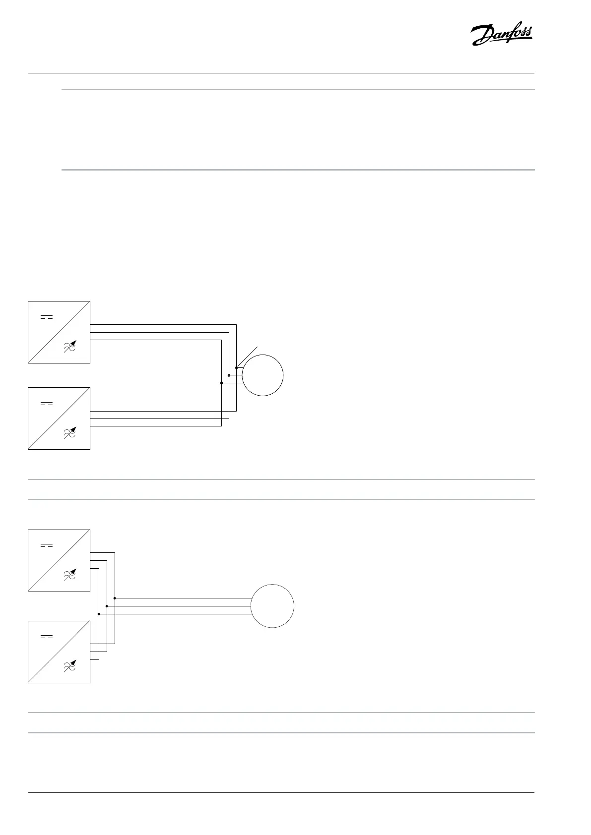
7.6 Recommended Installation of Motor Cables
If the power units are connected in parallel without output filters or only with a common-mode filter, the recommended common
coupling point of motor cables is at the motor terminals. It is also possible to use an alternative installation method where the common
coupling point of the motor cables is near the drives. In this case, to avoid current imbalance, the installation must be symmetrical and
the tolerance of cable length (impedance) to common coupling point is maximum 5%. If the cable connections are not symmetrical, use
a dU/dt filter or a sine-wave filter.
Figure 63: Recommended Installation
1 Inverter module 2 Common coupling point at the motor terminals
Figure 64: Alternative Installation Method
1 Inverter module
70 | Danfoss Drives Oy © 2024.03 AJ475942178716en-000101 / 172K2848A
Design Guide | iC7 Series Liquid-cooled System Modules
 Loading...


