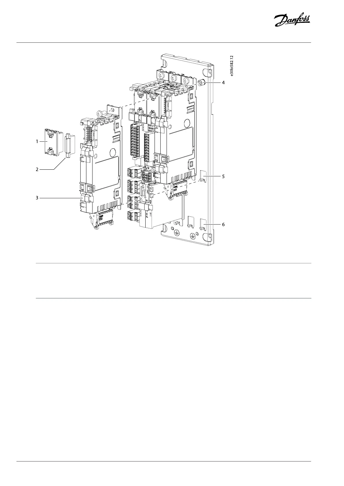
Figure 108: Installing a Board to the Modular Control Unit Mounting Plate
1 Option connector 2 Option terminal cover
3 Option board 4 Fixing point at the top
5 Fixing point at the middle 6 Fixing point at the bottom
3. Use the screw to attach the board to the fixing point at the top.
4. Attach an option connector to the newly installed board and the board next to it.
5. Attach option terminal covers to the empty terminals.
8.14 Connecting the Fieldbus Cable and the Fiber Cables
1. Connect the PLC to the Ethernet port X1 or X2 in the control board with a fieldbus cable.
2. Connect the terminal X80 in the control board to the terminal X90 in the star coupler board with a fiber cable.
3. Connect the terminals X301–X316 in the star coupler board to the power units with fiber cables.
110 | Danfoss Drives Oy © 2024.03 AJ475942178716en-000101 / 172K2848A
Design Guide | iC7 Series Liquid-cooled System Modules
 Loading...


