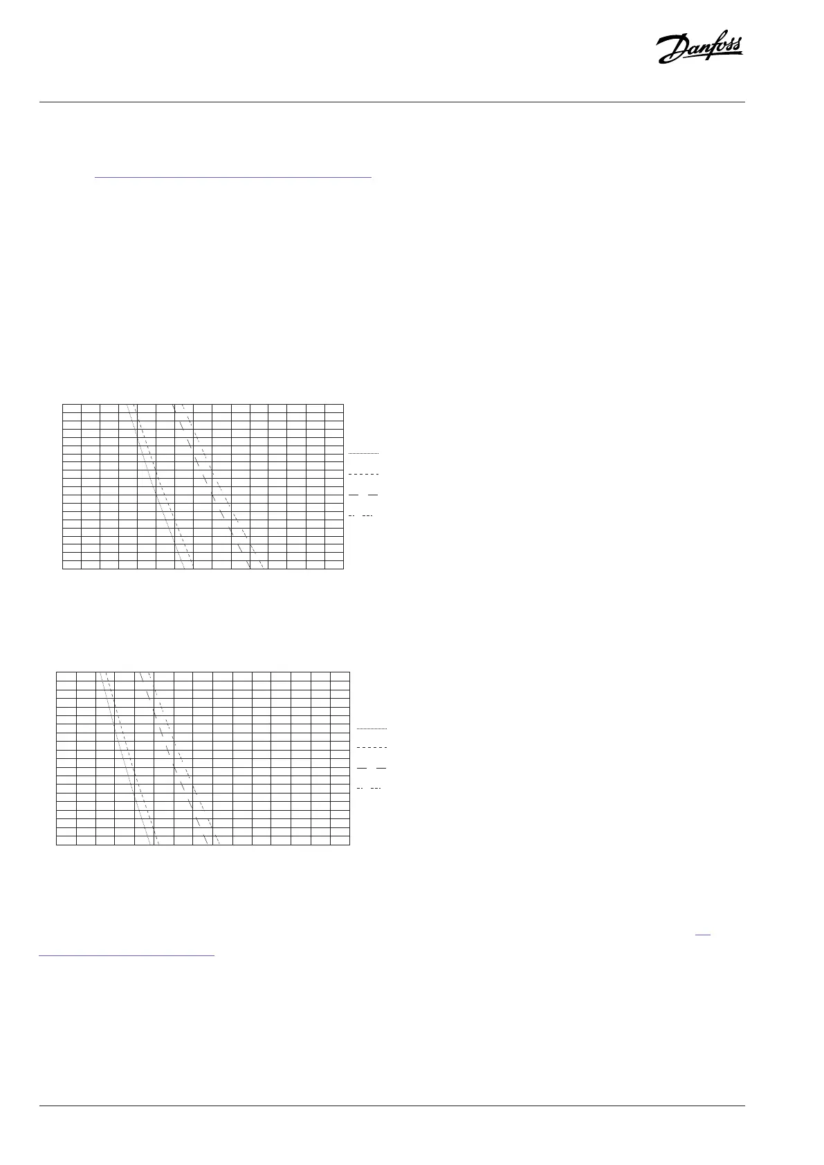
The maximum motor cable length depends mainly on switching frequency, DC-link voltage, and motor cable setup. Safe operation area
graphs are presented below for all available filter types. The motor cable length is based on the maximum number of cables for each
frame (see 10.4.4 Field Cable Sizes for INU Module, 525–690 V AC). For example, the graphs for a 416 A filter are based on two parallel
cables, and for an 820 A filter on four parallel cables. The default motor cable operating capacitance is 0.75 nF/m. If some other cable
type is used or the number of cables connected in parallel does not match with recommendations, the maximum motor cable length
must be derated so that the maximum total motor cable capacitance is not exceeded.
Losses are higher in low output frequency range (0–5 Hz). If drives are operating in this range, the maximum motor cable length
(capacitance) must be derated.
In an IT system, filter losses in a single-phase earth fault depend on the setup. All capacitances to ground should be minimized to
minimize the fault current. The fault current increases the losses, and continuous operation during the earth fault cannot be guaranteed,
especially if the filter is already in the limits without the fault. The filter has temperature protection against too high earth fault currents.
150 225
1122 VDC
Mod. 1
1122 VDC
Mod. 2
1025 VDC
Mod. 1
1025 VDC
Mod. 2
Figure 85: Safe Operation Area: 416 A Common-mode Filter
1122 VDC
Mod. 2
1025 VDC
Mod. 1
1025 VDC
Mod. 2
Figure 86: Safe Operation Area: 416 A Common-mode Filter, Low Output Frequency Range
If drives are connected in parallel, the recommended common connection point for motor cables is at the motor terminals. See 7.5
Prerequisites for Cable Installation.
84 | Danfoss Drives Oy © 2024.03 AJ475942178716en-000101 / 172K2848A
Design Guide | iC7 Series Liquid-cooled System Modules
 Loading...


