Design Guide | iC7 Series Liquid-cooled System Modules
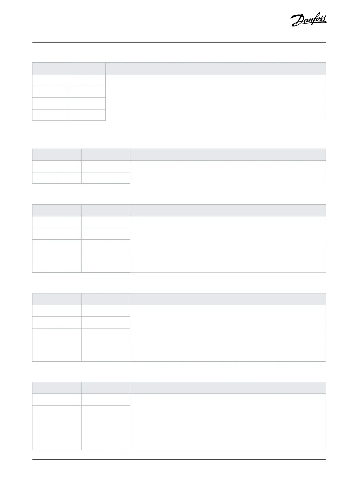
Table 29: I/O Terminal Signals (X13) (continued)
Terminal Function Description
35 GND
36 GND
37 GND
38 GND
I/O ground.
Ground for digital outputs, +10 V Ref, +24 V
out
, analog inputs, and analog outputs.
1) Digital outputs are not recommended for main circuit braker control, use relay outputs instead.
Table 30: Thermistor Input Signals (X51)
Terminal Function Description
71 TI+
72 TI-
Thermistor input, galvanically isolated. R
trip
= 4 kΩ
Table 31: Relay 1 Signals (X101)
Terminal Function Description
1 COM
2 NO
3 NC
Configurable relay output.
Switching capacity:
• 24 V DC/8 A
• 250 V AC/8 A
• 125 V DC/0.4 A
Minimum switching load: 5 V/10 mA
Table 32: Relay 2 Signals (X102)
Terminal Function Description
4 COM
5 NO
6 NC
Configurable relay output.
Switching capacity:
• 24 V DC/8 A
• 250 V AC/8 A
• 125 V DC/0.4 A
Minimum switching load: 5 V/10 mA
Table 33: Relay 3 Signals (X103)
Terminal Function Description
7 COM
8 NO
Configurable relay output.
Switching capacity:
• 24 V DC/8 A
• 250 V AC/8 A
• 125 V DC/0.4 A
Minimum switching load: 5 V/10 mA
Danfoss Drives Oy © 2024.03 AJ475942178716en-000101 / 172K2848A | 103
 Loading...


