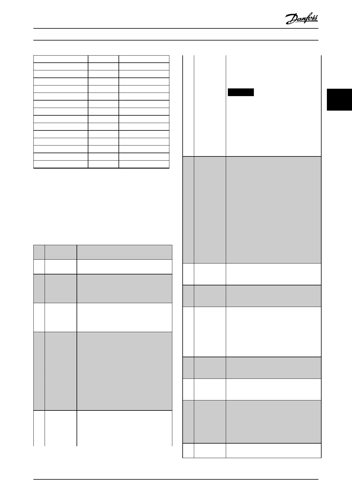
Digital input function Select Terminal
Counter A (up) [60] 29, 33
Counter A (down) [61] 29, 33
Reset counter A [62] All
Counter B (up) [63] 29, 33
Counter B (down) [64] 29, 33
Reset counter B [65] All
Sleep mode [66] All
Reset maintenance word [78] All
PTC card 1 [80] All
Lead pump start [120] All
Lead pump alternation [121] All
Pump 1 interlock [130] All
Pump 2 interlock [131] All
Pump 3 interlock [132] All
All=Terminals 18, 19, 27, 29, 32, 33, X30/2, X30/3, X30/4.
X30/ are the terminals on VLT
®
General Purpose I/O MCB
101.
Functions dedicated to only 1 digital input are stated in
the associated parameter.
All digital inputs can be programmed to these functions
[0] No operation No reaction to signals transmitted to
terminal.
[1] Reset Resets frequency converter after a trip/
alarm. Not all alarms can be reset.
[2] Coast inverse Leaves motor in free mode. Logic
0⇒coasting stop.
(Default Digital input 27): Coasting stop,
inverted input (NC).
[3] Coast and
reset inverse
Reset and coasting stop, inverted input (NC).
Leaves motor in free mode and resets the
frequency converter. Logic 0⇒coasting stop
and reset.
[5] DC-brake
inverse
Inverted input for DC braking (NC).
Stops motor by energizing it with a DC
current for a certain time period. See
parameter 2-01 DC Brake Current to
parameter 2-03 DC Brake Cut In Speed [RPM].
The function is only active when the value
in parameter 2-02 DC Braking Time is
dierent from 0. Logic 0⇒DC braking.
This selection is not possible when
parameter 1-10 Motor Construction is set to
[1] PM non-salient SPM.
[6] Stop inverse Stop inverted function. Generates a stop
function when the selected terminal goes
from logical level 1 to 0. The stop is
performed according to the selected ramp
time
•
Parameter 3-42 Ramp 1 Ramp Down
Time
•
Parameter 3-52 Ramp 2 Ramp Down
Time
NOTICE
When the frequency converter is at
the torque limit and has received a
stop command, it may not stop by
itself. To ensure that the frequency
converter stops, congure a digital
output to [27] Torque limit & stop and
connect this digital output to a digital
input that is congured as coast.
[7] External
Interlock
Same function as coasting inverse and stop
inverse, but this option generates the alarm
message External fault on the display when
the terminal programmed for coast inverse
has signal 0. The alarm message is also
active via digital outputs and relay outputs,
if programmed for external interlock. When
the external interlock is removed, the alarm
can be reset using a digital input or the
[RESET] key. A delay can be programmed in
parameter 22-00 External Interlock Delay.
After applying a signal to the input, the
reaction described above is delayed with the
time set in parameter 22-00 External Interlock
Delay.
[8] Start Select start for a start/stop command. Logic
1=start, logic 0=stop.
(Default: Digital input 18).
[9] Latched start The motor starts, if a pulse is applied for
minimum. 2 ms. The motor stops when stop
inverse is activated.
[10] Reversing Changes direction of motor shaft rotation.
Select Logic 1 to reverse. The reversing
signal only changes the direction of rotation.
It does not activate the start function. Select
both directions in parameter 4-10 Motor
Speed Direction.
(Default: Digital input 19).
[11] Start
reversing
Used for start/stop and for reversing on the
same wire. Signals on start are not allowed
at the same time.
[14] Jog Used for activating jog speed. See
parameter 3-11 Jog Speed [Hz].
(Default: Digital input 29)
[15] Preset
reference on
Used for shifting between external reference
and preset reference. It is assumed that
External/preset [1] has been selected in
parameter 3-04 Reference Function. Logic
0=external reference active; logic 1=1 of the
8 preset references is active.
[16] Preset ref bit
0
Enables a choice between 1 of the 8 preset
references according to Table 3.13.
Parameter Descriptions Programming Guide
M0010001 Danfoss A/S © 10/2019 All rights reserved. 87
3 3
 Loading...


