MATRIX 210™ REFERENCE MANUAL
10 TROUBLESHOOTING
10.1 GENERAL GUIDELINES
When wiring the device, pay careful attention to the signal name (acronym) on the
CBX100/500 spring clamp connectors (chp. 4). If you are connecting directly to the
Matrix 210™ 25-pin male D-sub connector pay attention to the pin number of the signals
(chp. 5).
If you need information about a certain reader parameter you can refer to the VisiSet
program help files. Either connect the device and select the parameter you’re interested in
by pressing the F1 key, or select Help>Paramters Help from the command menu.
If you’re unable to fix the problem and you’re going to contact your local Datalogic office or
Datalogic Partner or ARC, we suggest providing (if possible): Application Program version,
Parameter Configuration file, Serial Number and Order Number of your reader. You can
get this information while VisiSet™ is connected to the reader: the Application Program
version is shown in the Terminal Window; the Parameter Configuration can be saved to an
.ini file applying the File>Save Configuration File command in the Parameter Setup
window; Serial Number and Order Number can be obtained by applying the respective
command in the Tools menu.
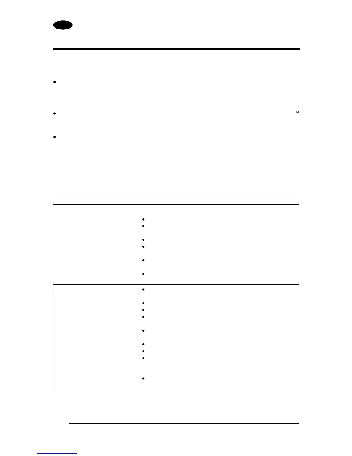
Power ON:
the “POWER” LED is not lit.
Is power connected?
If using a power adapter (like PG6000), is it connected
to wall outlet?
If using rail power, does rail have power?
If using CBX, does it have power (check switch and
LED)?
Check if you are referring to the 25-pin connector or to
the CBX spring clamp connectors.
Measure Voltage either at pin 13 and pin 25 (for 25-pin
connector) or at spring clamp Vdc and GND (for CBX).
One Shot or Phase Mode
using the Input 1 (External
Trigger) or Input 2:
the ”TRIGGER” LED is not
blinking while the External
Trigger is switching.
Check if you are referring to the 25-pin connector or to
the CBX spring clamp connectors.
Is the sensor connected to the Input 1 or Input 2?
Is power supplied to the photo sensor?
For NPN configuration, is power supplied to one of the
two I1 or I2 signals (A or B)?
For PNP configuration, is one of the two I1 or I2 signals
grounded (A or B)?
Are the photo sensor LEDS (if any) working correctly?
Is the sensor/reflector system aligned (if present)?
In the Digital I/O folder check the EXTERNAL
TRIGGER or INPUT 2\Debounce Filter parameter
setting.
In the Operating Mode folder check the settings for
Reading Phase-ON, Acquisition Trigger and
Reading Phase-OFF parameters.
 Loading...