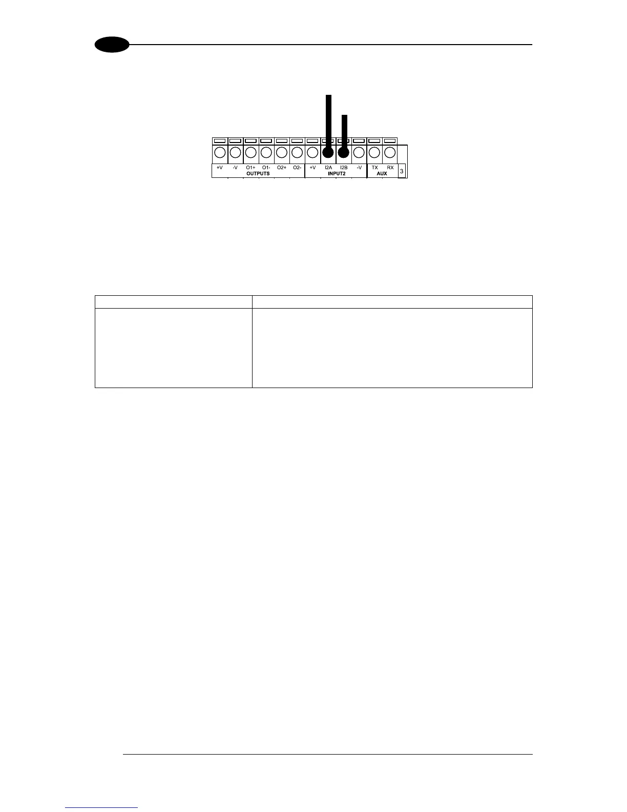
Figure 55 - NPN Input 2 Using External Power
4.6 OUTPUTS
Two optocoupled general purpose outputs are available. The meaning of the two outputs
Output 1 and Output 2 can be defined by the user. They are typically used either to signal the
data collection result or to control an external lighting system.
The electrical features of the two outputs are the following:
V
CE
= 30 Vdc max.
I
CE
= 40 mA continuous max.; 130 mA pulsed max.
By default, Output 1 is associated with the Partial Read and No Read events, which activates
when the code(s) signaled by the external trigger are not decoded, and Output 2 is
associated with the Complete Read event, which activates when all the selected codes are
correctly decoded.
The output signals are fully programmable being determined by the configured
Activation/Deactivation events, Deactivation Timeout or a combination of the two. Refer to
the Digital I/O folder in the VisiSet™ Help On Line for further details.
 Loading...