MATRIX 210™ REFERENCE MANUAL
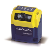
INPUT 2 CONNECTIONS USING EXTERNAL POWER
Figure 83 - PNP Input 2 Using External Power
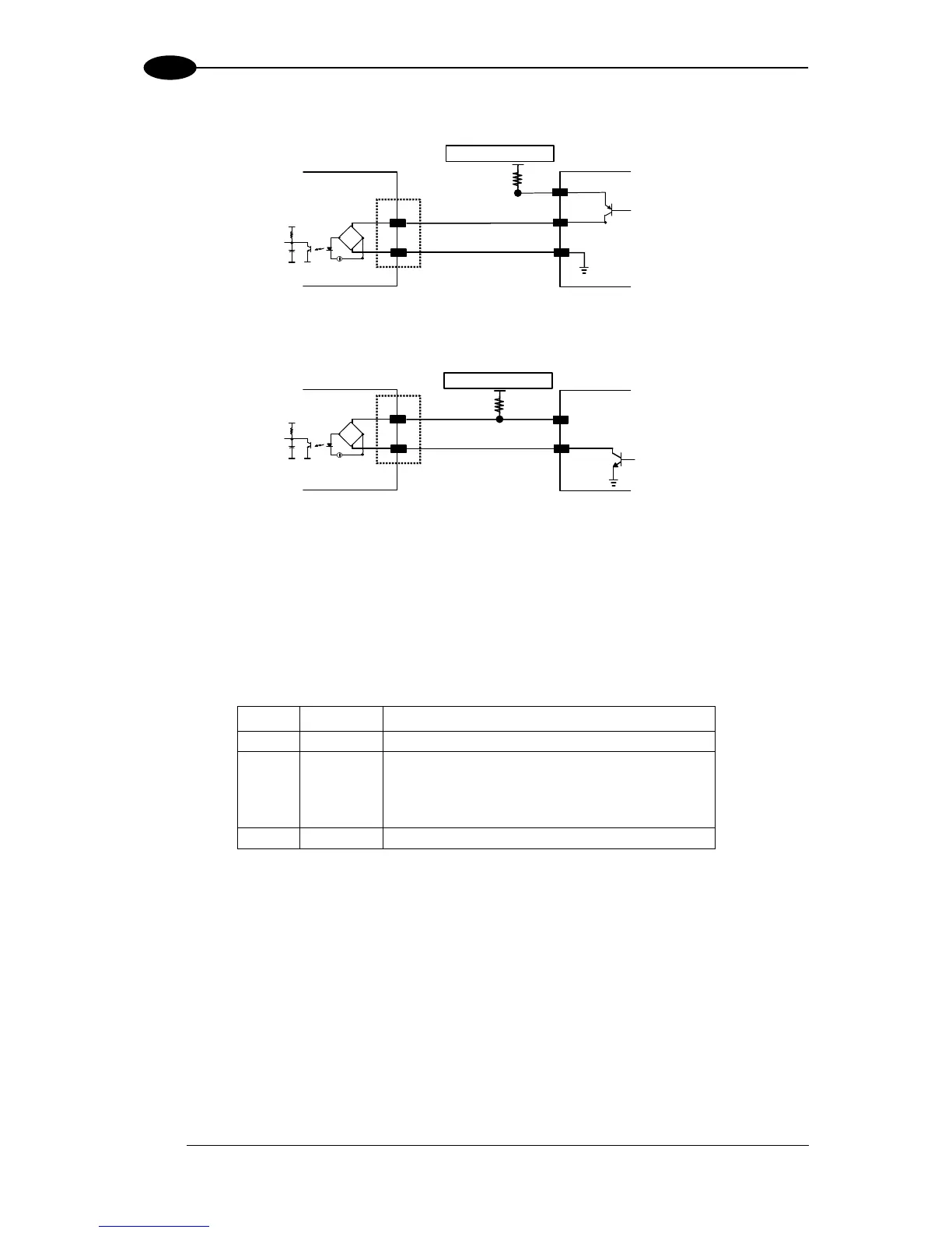
Figure 84 - NPN Input 2 Using External Power
5.9 OUTPUTS
Two opto-coupled general purpose outputs are available on the 25-pin connector. The
meaning of the two outputs Output 1 and Output 2 can be defined by the user. They are
typically used either to signal the data collection result.
The pinout is the following:
Power Supply input voltage +
Configurable digital output 1 - positive pin
Configurable digital output 1 - negative pin
Configurable digital output 2 - positive pin
Configurable digital output 2 - negative pin
Power Supply input voltage -
The electrical features of the two outputs are the following:
VB
CE
B
max = 30 Vdc
I max = 40 mA continuous; 130 mA pulsed
By default, Output 1 is associated with the Partial Read and No Read events, which activates
when the code(s) signaled by the external trigger are not decoded, and Output 2 is
associated with the Complete Read event, which activates when all the selected codes are
correctly decoded.
 Loading...