EasyManuals Logo
Home>Datalogic>Barcode Reader>Matrix 210

Datalogic Matrix 210 User Manual

Datalogic Matrix 210
142 pages
To Next Page IconTo Next Page
To Previous Page IconTo Previous Page
Page #47 background imageLoading...
Page #47 background image
INSTALLATION
37
3
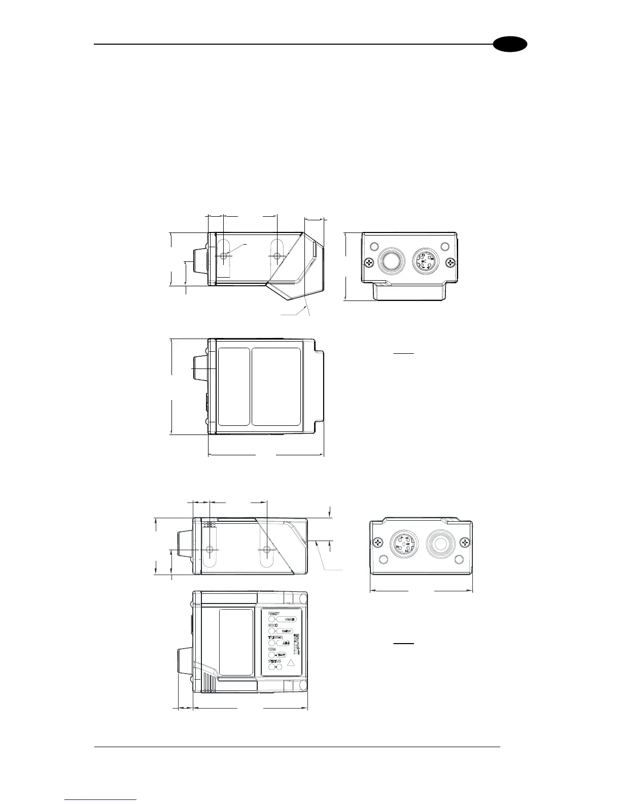
3.2 MECHANICAL DIMENSIONS
Matrix 210™ can be installed to operate in different positions. The four screw holes (M3 x 4)
on the body of the reader are for mechanical fixture (Figure 27).
The diagram below gives the overall dimensions of the reader and may be used for its
installation.
Refer to par. 3.3 for various mounting solutions and correct positioning and chp. 7 for
Reading Distance considerations.
32
[1.25]
9.0
[0.36]
25.0
[0.98]
7
[0.29]
M3X4
n°4
25
[0.98]
45
[1.76]
54
[2.13]
11
[0.45]
Figure 27 Straight Model Overall Dimensions
45
[1.76]
10.0
[0.39]
25.0
[0.98]
11.0
[0.43]
25
[0.98]
50
[1.97]
7
[0.29]
6
[0.25]
Figure 28 90° Model Overall Dimensions
mm
[in]
mm
[in]
Optical axis
Optical axis

Table of Contents

Other manuals for Datalogic Matrix 210

Questions and Answers:

Question and Answer IconNeed help?

Do you have a question about the Datalogic Matrix 210 and is the answer not in the manual?

Datalogic Matrix 210 Specifications

General IconGeneral
BrandDatalogic
ModelMatrix 210
CategoryBarcode Reader
LanguageEnglish

Related product manuals