MATRIX 210™ REFERENCE MANUAL
2.2 INDICATORS AND KEYPAD BUTTON
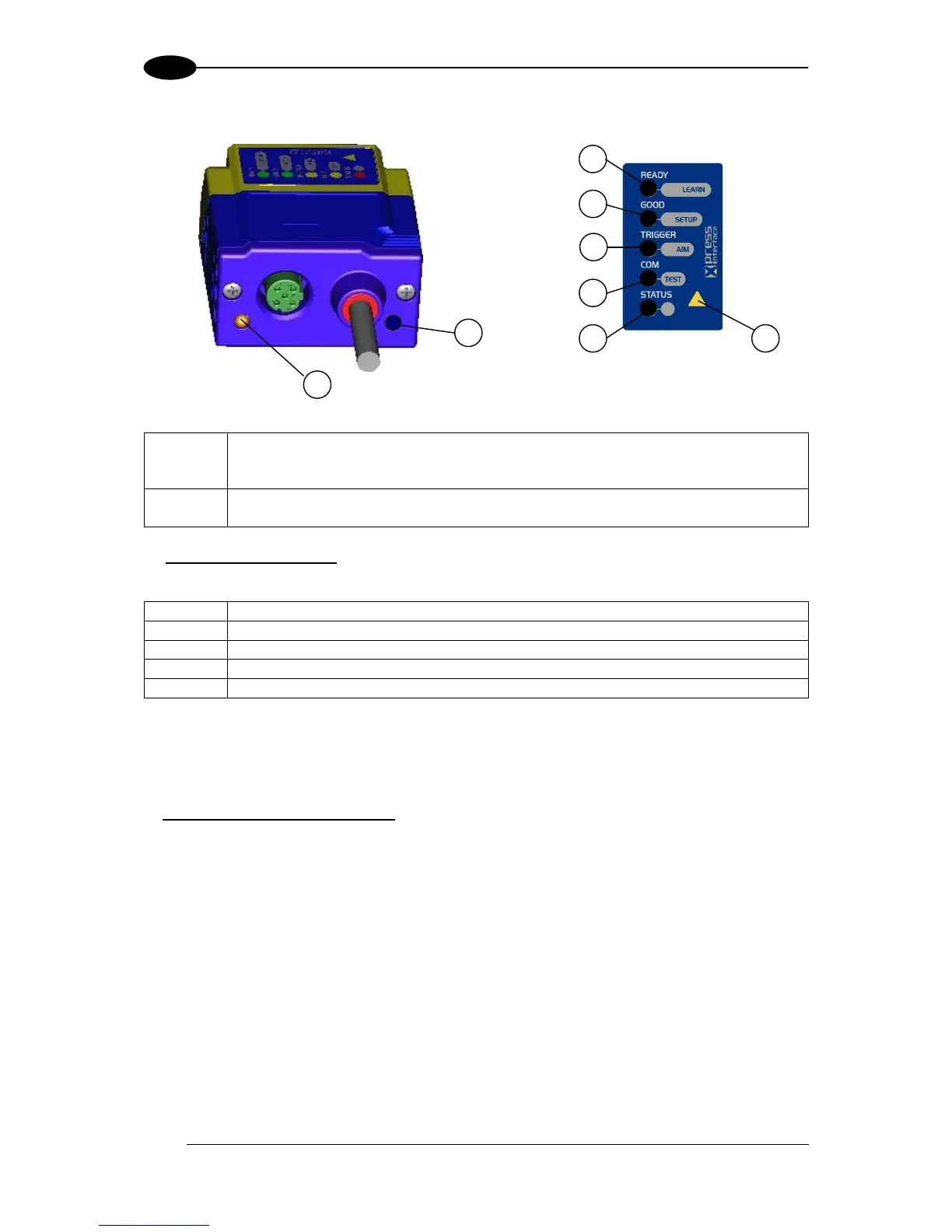
Figure 15 - Indicators
The following LED indicators are located on the reader:
For Ethernet models, on the connector side of the reader near the Ethernet
connector, the orange ETHERNET NETWORK PRESENCE LED indicates the
on-board Ethernet network connection. (Figure 15, 1)
On the connector side of the reader near the cable, the blue POWER ON LED
indicates the reader is correctly powered. (Figure 15, 2)
In normal operating mode the colors and meaning of the five LEDs are illustrated in the
following table:
green LED indicates that the reader is ready to operate (Figure 15, 3)
green LED confirms successful reading (Figure 15, 4)
yellow LED indicates the status of the reading phase (Figure 15, 5)
yellow LED indicates active communication on the main serial port * (Figure 15, 6)
red LED indicates a NO READ result (Figure 15, 7)
* When connected to a Fieldbus network through the CBX500, the COM LED is always active, even in the
absence of data transmission, because of polling activity on the Fieldbus network.
During the reader startup (reset or restart phase), these five LEDs blink for one second.
In X-PRESS™ Configuration mode the colors and meaning of these five LEDs are described
in par. 2.4.
The keypad button (Figure 15, 8, is software programmable. By default it starts the X-
PRESS™ interface for quick installation without using a PC (see chp. 1).
 Loading...