4. Remove the backplane cover.
5. Remove the air shroud.
6. Disconnect the VGA cable from the VGA connector on the system board. For locating the connector, see the System board jumpers
and connecters section.
NOTE: Ensure that you note the routing of the cables as you remove them from the system board. Route these cables
properly when you replace them to prevent them from being pinched or crimped.
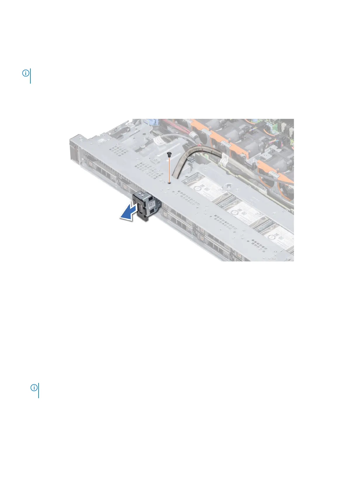
Steps
1. Using Phillips #1 screwdriver, remove the screw on the VGA module.
2. Slide the module out of the system.
Figure 102. Removing the VGA module
Next steps
1. Install the VGA module.
Installing the VGA module
Prerequisites
1. Follow the safety guidelines listed in Safety instructions on page 71.
2. Follow the procedure listed in Before working inside your system on page 72.
3. Remove the front bezel.
4. Remove the backplane cover.
5. Remove the air shroud.
NOTE:
Ensure that you note the routing of the cables as you remove them from the system board. Route these
cables properly when you replace them to prevent them from being pinched or crimped.
Steps
1. Route the VGA cable through the VGA module slot on the front of the system and slide the VGA module into the slot.
2. Align the hole on the module with the screw hole on the system.
3. Using the Phillips #1 screwdriver, secure the VGA module to the system with the screw.
Installing and removing system components
149
 Loading...