AH Motion – Hardware Manual
3-8
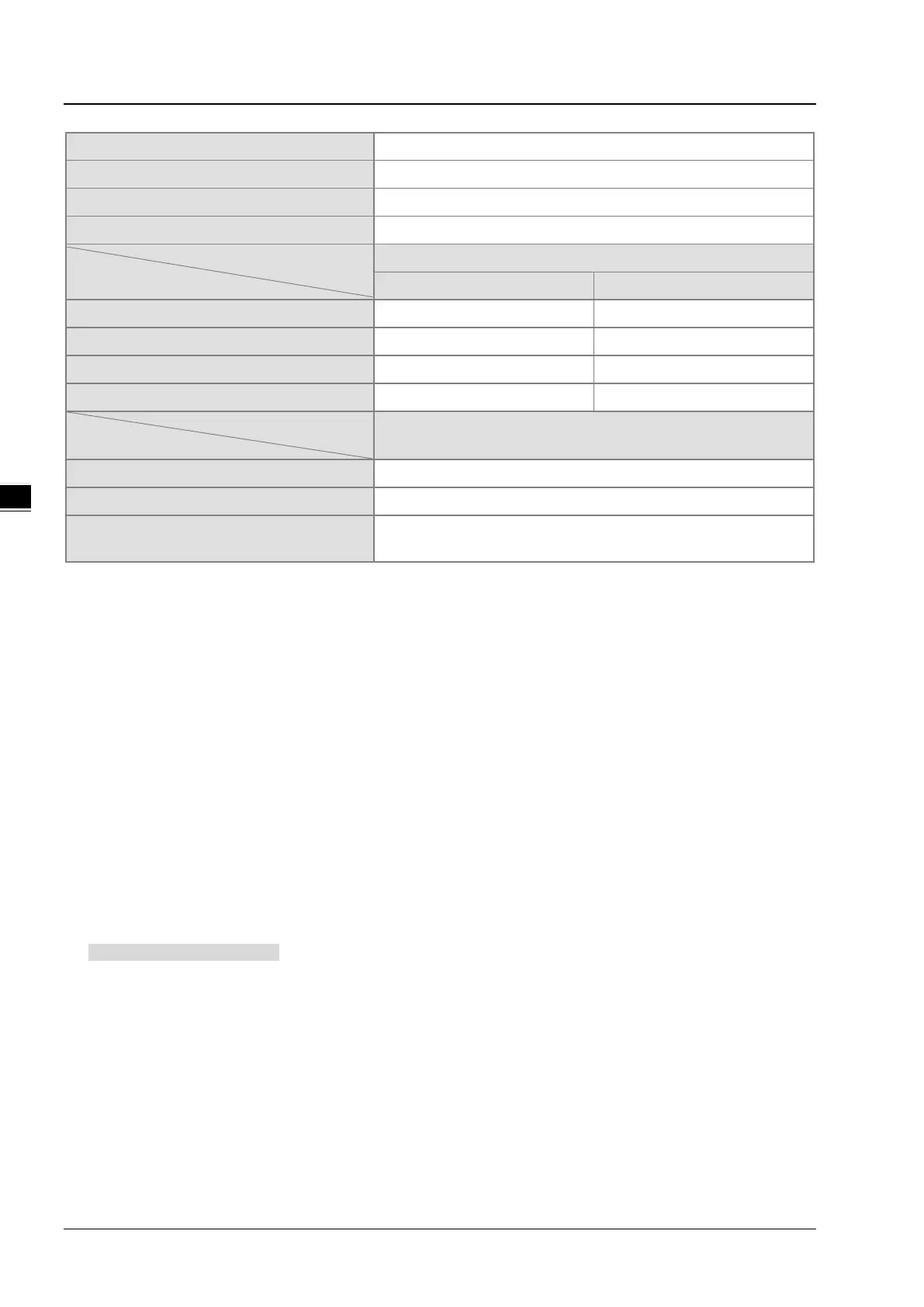
Slave stations are supported.
Slave stations are supported.
Number of data read/written (ASCII mode)
Number of data read/written (RTU mode)
Interface
Specifications
10/100 Mbps 10/100 Mbps
MODBUS TCP EtherNet/IP
Number of data read/written
100 registers 250 registers
Maximum transmission distance
100 meters 100 meters
Interface
EtherCAT
100 Mbps
EtherCAT packet format
Number of axes supported
AH08EMC-5A: 8 axes; AH10EMC-5A: 16 axes; AH20EMC-5A: 32
axes
3.2.4 I/O Addressing of AH Motion CPU
The I/O addressing between AH Motion CPUs and AH500 I/O modules installed on the motion backplane is a part of the
CPU specifications. The range of I/O addressing of AH Motion CPUs is explained in this section.
Software-defined address
Every AH motion CPU supports software-defined addresses between AH Motion CPU and its I/O modules. As a
default setting, a starting address is given by the software and I/O addresses are automatically allocated according to
the starting address. For example, AH16AM10N-5A, digital input module with 16 inputs, takes the input device range
of 16 bits, starting from Xn.0 (Xn.0~Xn.15).
User-defined address
If you want to define the I/O addresses according to actual needs, you can assign a starting address to an input/output
module by software. You can benefit from the user-defined addresses that allow you to obtain a flexible and
customized program. The available user-defined addresses for each I/O module will be listed later.
Software-defined Addresses
Digital Input/Output Modules
Input/Output devices are automatically assigned to a digital input/output module through HWCONFIG in ISPSoft
according to the number of inputs/outputs which the digital input/output module has. The default start addresses are
shown below.
Note:
1. The below diagram only shows the list of the modules and is not an actual configuration.
2. AH16AR10N-5A(16AR) is not supported.
 Loading...


