Chapter 12 Description of Parameter SettingsC2000
12.1-14-3
Analog Output 1 Gain (AO10)
Analog Output 1 Gain (AO11)
Default: 100.0
Settings 0.0–500.0%
Adjusts the voltage level outputted to the analog meter from the analog signal (Pr. 14-12,
Pr. 14-13) output terminal AFM of the drive.
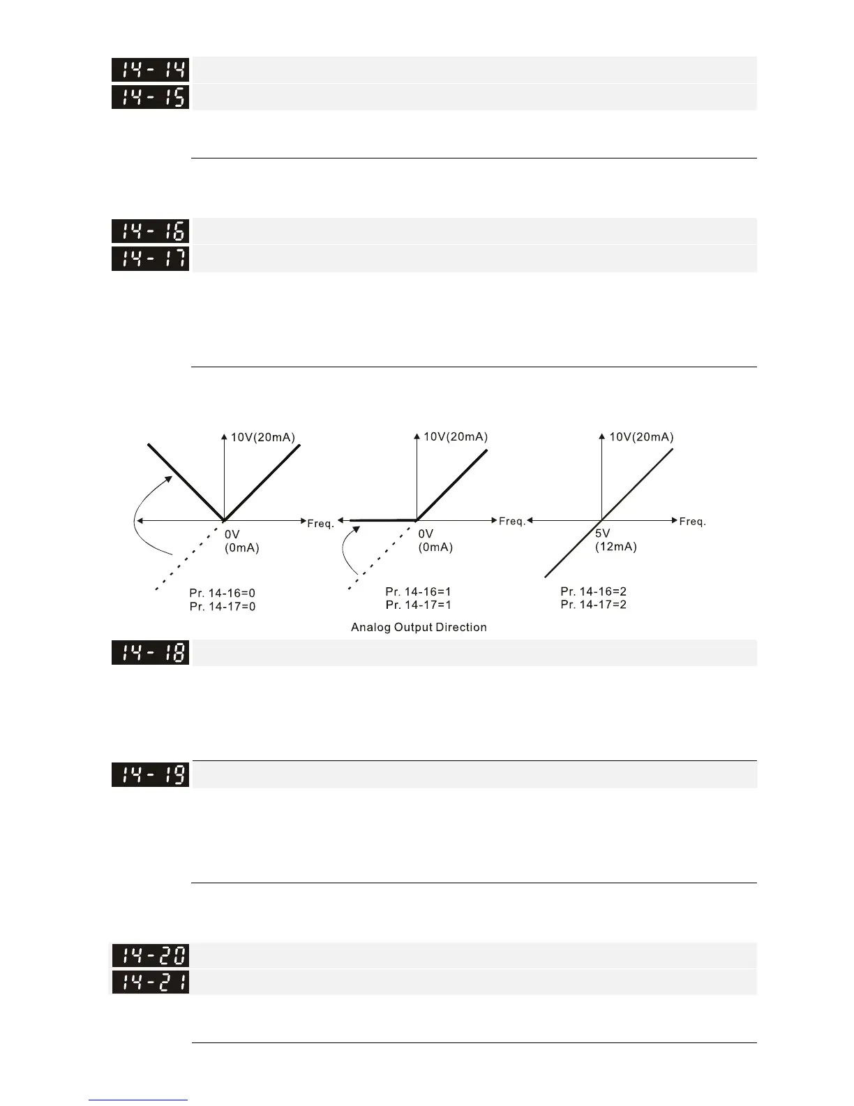
Analog Output 1 in REV Direction (AO10)
Analog Output 1 in REV Direction (AO11)
Default: 0
Settings 0: Absolute output voltage value
1: Reverse output 0V; forward output 0–10V
2: Reverse output 5–0V; forward output 5–10V
Determines the voltage reverse output when AO10 and AO11 are set as 0–10 V (Pr. 14-36 = 2,
Pr. 14-37 = 2).
Extension Card Input Selection (AI10)
Default: 0
Settings 0: 0–10V (AVI10)
1: 0–20mA (ACI10)
2: 4–20mA (ACI10)
Extension Card Input Selection (AI11)
Default: 0
Settings 0: 0–10V (AVI11)
1: 0–20mA (ACI11)
2: 4–20mA (ACI11)
When you change the input mode, verify that the switch position of external terminal (AI10, AI11)
is correct.
AO10 DC Output Setting Level
AO11 DC Output Setting Level
Default: 0.00
Settings 0.00–100.00%
 Loading...