INSTALLATION
3-8 EPT019297 Issue 1 November 2016
Product Sensor / Shaft Encoder PNP and NPN Selection
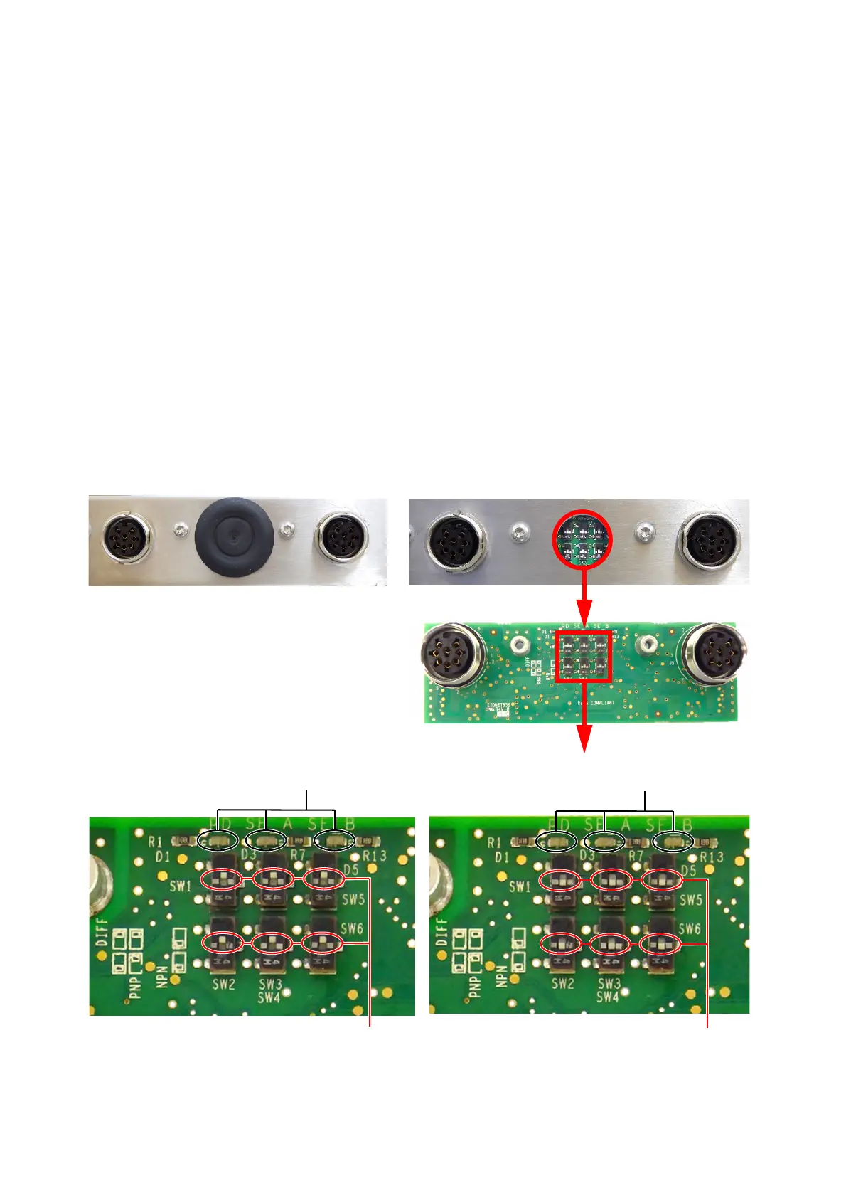
The picture below shows the PD/SE Printed Circuit Board with Lumberg connector and the
PNP/NPN switches. The configuration of these switches will set the product sensor and shaft
encoder inputs to either PNP or NPN. There are LED’s on the PCB to indicate that the signal is
correct.
The board is located at the rear of the Ax350i/Ax550i printer cabinet or on the left side of the
Ax150i printer cabinet. The switches are accessed by removing the rubber grommet shown
below.
Note: The rubber grommet must be replaced to maintain the printer cabinet’s IP rating.
Normally a single channel shaft encoder is used, using Channel A.
When a quadrature shaft encoder is used the Channels SE-A + SE-B can be utilised.
For information on the settings:
PD = Product Detect Sourcing = NPN Configuration
SE A = Shaft Encoder 1 Sinking = PNP Configuration
SE B = Shaft Encoder 2
The switches above are set to PNP The switches above are set to NPN
LEDs
LEDs
 Loading...