INSTALLATION
A-20 20509 Issue 7 Jan 2018
Disconnect the blanking plug from a print head connection port on the ink
manifold assembly. Loop the new feed pipe once and cut to length
(ensuring the pipe is not too tight). Fit the feed pipe to the connector using
the nut from the blanking plug.
When a new print head is added it will be necessary to add an intensity
control.
(1) Remove the blanking plug from the hole with the number
corresponding to the new print head.
(2) Fit the intensity control into the rear panel.
(3) Connect the intensity control to PL2 on the mother board. For
connection details see the opposite page.
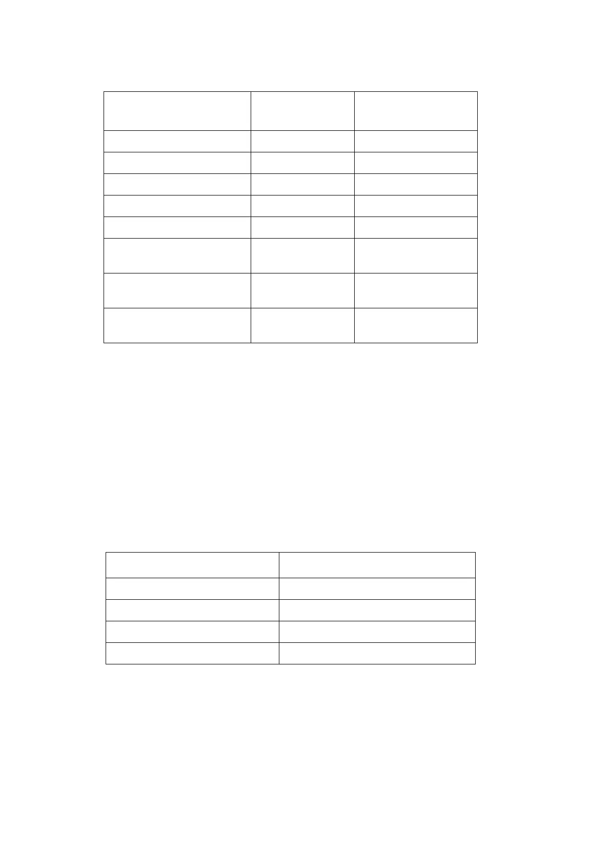
When adding the following combination of heads it will be necessary to add
a second solenoid driver PCB:
Solenoid Driver PCB 1 supplies SK1 and SK2. The additional Solenoid
Driver PCB 2 supplies SK3 and SK4. Before adding the second Solenoid
Driver PCB, check that the links are set up correctly (see
page 4-37).
EXISTING PRINT
HEAD(S)
NEW PRINT
HEAD
MOTHERBOARD
SOCKET
1 x 7 nozzle head 1 x 7 nozzle head SK2
2 x 7 nozzle heads 1 x 7 nozzle head SK3
3 x 7 nozzle heads 1 x 7 nozzle head SK4
1 x 16 nozzle head 1 x 7 nozzle head SK3
1 x 16 & 1 x 7 nozzle head 1 x 7 nozzle head SK4
1 x 16 nozzle head 1 x 16 nozzle
head
SK3
1 x 7 nozzle head 1 x 16 nozzle
head
SK3
2 x 7 nozzle heads 1 x 16 nozzle
head
SK3
EXISTING PRINT HEADS NEW PRINT HEAD
2 x 7 nozzle head 1 x 7 nozzle head
1 x 16 nozzle head 1 x 7 nozzle head
1 x 16 nozzle head 1 x 16 nozzle head
1 x 7 nozzle head 1 x 16 nozzle head
 Loading...