Maintenance Manual (960-945) 4-34
Replacement Procedures
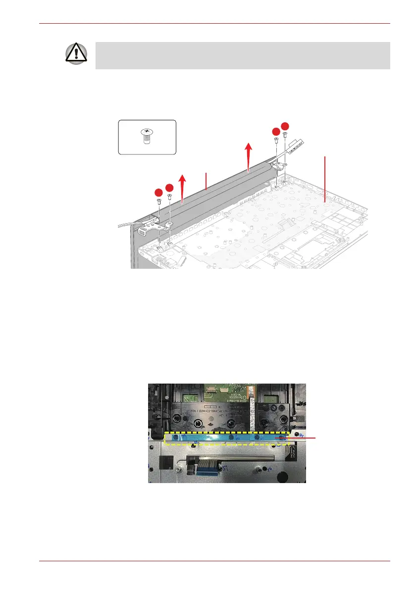
1. Release the following screws and separate the LCD Assembly and
Cover Assembly.
Figure 4-37 Removing the Keyboard/Cover Assembly
4.26.2 Installing the Keyboard/Cover Assembly
To install the Keyboard/Cover Assembly, follow the step below and refer to
Figure 4-37.
1. Set the LCD Assembly on the Cover Assembly and secure them with
the screws.
Note: When replacing the Cover Assembly with a new one
■ Stick the D TAPE on the cover assembly in place and remove the
separator on it.
■ Stick one piece of GASKET on the cover assembly in place.
As the keytop may fall out, when handling the keyboard, always hold it by
the frame and do not touch the key top.
F2.5x5BT
LCD Assembly
Cover Assembly
2
1
3
4
 Loading...