Options for Discrete Output Source (continued)Table 6-4:
Option
Label
State
Discrete output volt-
ageProLink III Field Communicator
OFF 0 V
Fault (default) Fault Indicator Fault ON Site-specific
OFF 0 V
Important
This table assumes that Discrete Output Polarity is set to Active High. If Discrete Output Polarity is set to Active
Low, reverse the voltage values.
Related information
Configure an enhanced event
Fault indication with the discrete output
6.3.2 Configure Discrete Output Polarity
Display OFF-LINE MAINT > OFF-LINE CONFG > IO > CH B > DO > CONFIG DO > DO POLAR
ProLink III Device Tools > Configuration > I/O > Outputs > Discrete Output
Field Communicator Configure > Manual Setup > Inputs/Outputs > Discrete Output > DO Polarity
Overview
Discrete outputs have two states: ON (active) and OFF (inactive). Two different voltage
levels are used to represent these states. Discrete Output Polarity controls which voltage level
represents which state.
Procedure
Set Discrete Output Polarity as desired.
The default setting is Active High.
Options for Discrete Output Polarity
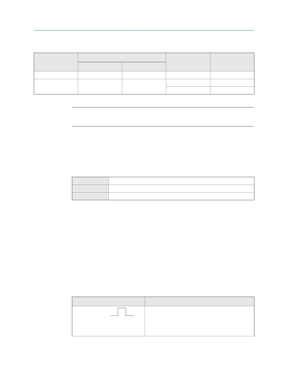
Options for Discrete Output PolarityTable 6-5:
Polarity Description
Active High • When asserted (condition tied to DO is true), the cir-
cuit draws as much current as it can, up to a maximum
of 10 mA.
• When not asserted (condition tied to DO is false), the
circuit draws less than 1 mA.
Integrate the meter with the control system
Configuration and Use Manual 85

 Loading...