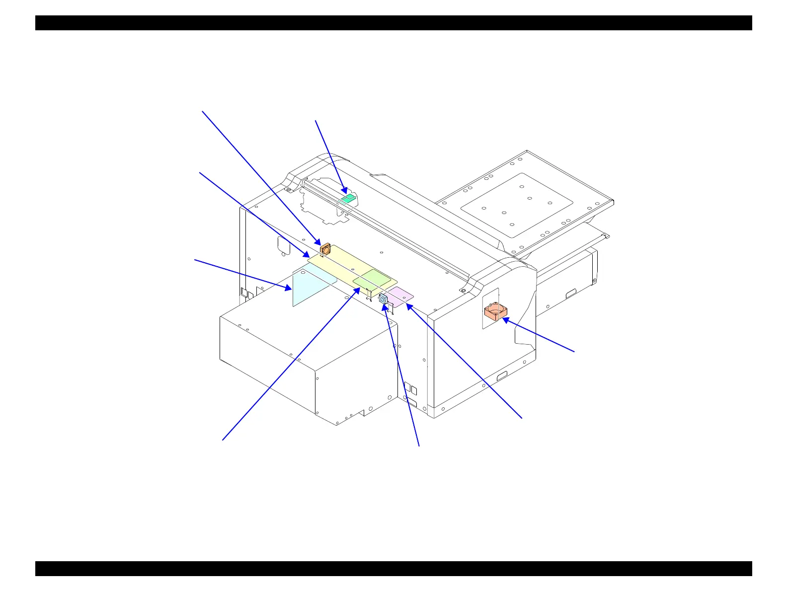
Figure 3-4. Electric Circuit Components / Fans
CR SUB BOARD (p. 102)
Relays the connection between the MAIN BOARD and
electric parts components. See “6.2 Connection Diagram
(p302)” for specific connections to the concerning parts/
components.
MAIN BOARD (p. 95)
• Communicates with the computer.
• Processes received data.
• Controls the printer mechanism.
• Stores the correction values and various
counters.
POWER SUPPLY BOARD (p. 99)
Generates the DC voltage for this
printer from the AC power supply.
SUB-B BOARD (p. 98)
Relays the connection between the MAIN BOARD
and electric parts components. See “6.2 Connection
Diagram (p302)” for specific connections to the
concerning parts/components.
MAIN-B BOARD (p. 97)
Communicates across anetwork.
DUCT FAN ASSY (p. 190)
Cools the air inside the printer.
BOARD BOX FAN 1 (p. 188)
Cools the air inside the Board Box.
BOARD BOX FAN 2 (p. 189)
Cools the air inside the Board Box.
 Loading...