SC-F2000 Revision C
DISASSEMBLY & ASSEMBLY Disassembly and Assembly Procedure 99
Confidential
3.4.4.4 POWER SUPPLY BOARD
1. Remove the PRINTER COVER. (p72)
2. Remove the RIGHT HOUSING PLATE. (p74)
3. Remove the RIGHT COVER ASSY. (p88)
4. Remove the LEFT HOUSING PLATE. (p73)
5. Remove the LEFT COVER ASSY. (p86)
6. Remove the REAR COVER SUB ASSY. (p77)
7. Remove the REAR COVER. (p79)
8. Remove the RIGHT IC COVER. (p83)
9. Remove the RIGHT IH COVER. (p85)
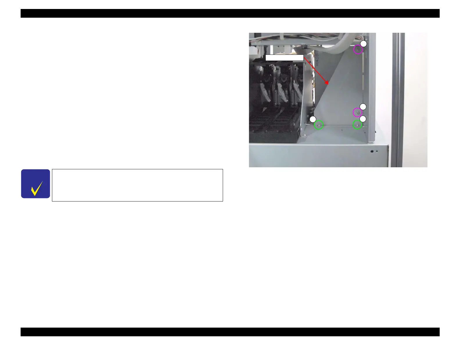
10. Remove the four screws, and remove the Right Sub Frame.
A) Silver M3x6 Cup S-tite screw: 2 pcs
B) Silver M3x6 Cup S-tite screw: 2 pcs
Figure 3-45. Removing the Right Sub Frame
When removing the screw B, use a stubby screwdriver.
 Loading...