Operation Manual
Version: 12/01
57
er900L Operation Manual
Art-Nr: 475.043
Ergometer
Type er900L
Appendix A: Interfaces
The ergometer er900L features a number of interfaces. Data can be transmitted or received
by the ergometer in analog or digital modes. Complete external control of the ergometer from
a PC or ECG is possible via these interfaces. These same interfaces also capable of trans-
ferring information to external devices (PC or ECG). ergoline provides a wide palette of
control variations using a variety of control protocols with a combination of analog and digital
signals. These protocols permit the ergometer’s connection to practically all ECG units on
the market that have an ergometric program. You will find the interface protocols in this ap-
pendix.
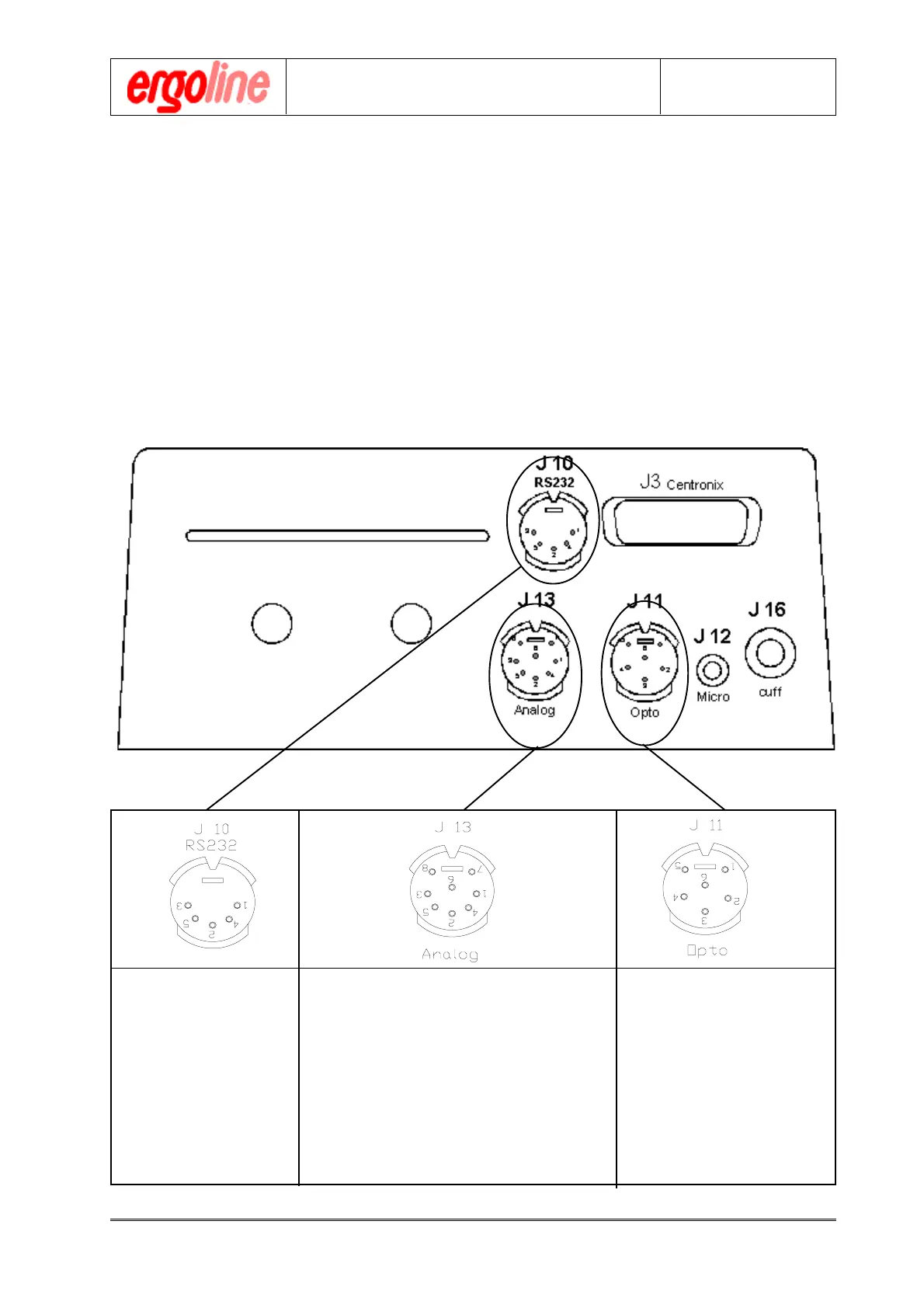
A.1 Input and Output Pin Specifications
Appendix A: Interfaces
Pin1 = TxD Pin1 = External Load Pin1 = +5V
Analog
Pin2 = GND Pin2 = Remote Start BPM Pin2 = EKG input.
Pin3 = RTS Pin3 = Remote Start EKG Pin3 = NC
Pin4 = CTS Pin4 = Pulse output Pin4 = NC
Pin5 = RxD Pin5 = Load output Pin5 = Opto input
Pin6 = Diastole output Pin6 = GND
Analog
Pin7 = ECG input
Pin8 = Systole output
Housing = GND
Inputs = Kursiv Outputs = Normal
 Loading...