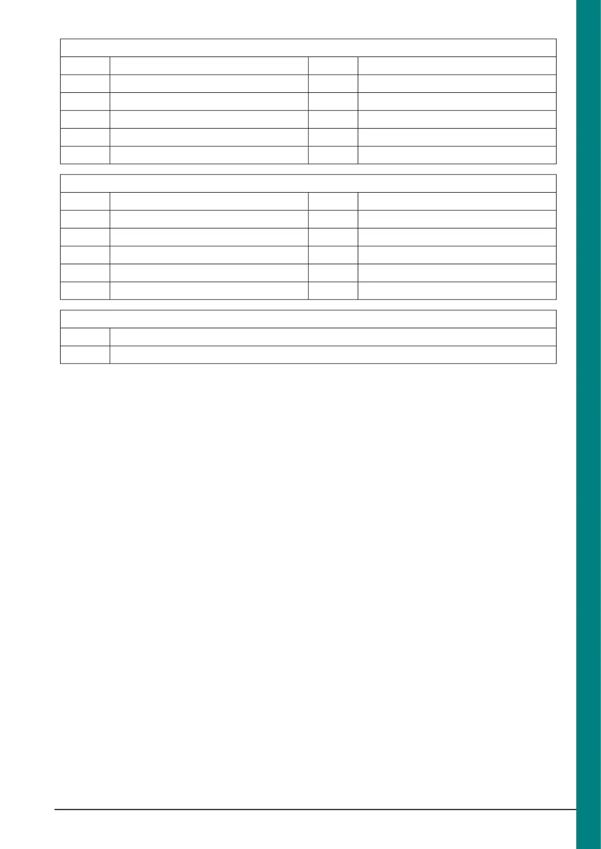
Connector B
Mono -7Mono +1
Radio Remote Control Ground8Switched Accessory +2
Auxiliary Left -9Auxiliary Left +3
Auxiliary Right -10Auxiliary Right +4
-11Phone Transceiver Active5
-12Radio Remote Control +6
Connector C
-7-1
-8-2
-9-3
-10-4
Auxiliary 2 Right11Auxiliary 2 Left5
-12Audio Ground6
Fuse Relay
no fuse is fitted to the radio1
no fuse is fitted to the radio2
4.9.2 Possible Accessories
Electric Antenna- Activation line, pin B2
(Switched Accessory +) is switched: 0 Volts when
the radio is switched off and +12 Volts when the
radio is switched on.
Auxiliary Input- Accepts a line-out from a
personal stereo or digital media player. This can
be supported by left channel pin C5 (+) and right
channel pin C11 (+) with a common ground, pin
C6, wired to a jack plug socket.
Audio Mute- There is a requirement under the
Health and Safety Machinery Directive to mute
the radio when machinery is in operation - this is
necessary to hear audible alarms and signals.
Pin B5 (C3-5 on the electrical schematic) on the
FAKRA interface should be used for this. In order
to avoid electrical issues due to leakage, and to
ensure connector compatibility, a connector
insert and a pre-crimped wire and terminal are
available as part of a wiring accessory kit, should
be used (Kit Part number KT6C1V-14A411-L*).
NOTE: When this line is pulled low (ground),
radio / CD sound is muted. However, there is no
wire present in the harness as this function is
normally communicated through the CAN bus.
Refer to: 4.14 Special Conversions (page 131).
(Adding Connectors, Terminals and Wiring)
After Market Hands Free Telephone Kit
(Non CAN-based)- Power should be supplied
via a fused battery line and activated by the
accessory line, pin A16. The mute line from the
phone is connected to Phone Transceiver Active,
pin B5. The audio output from the phone kit
should be fed into pins B1 (+) and B7 (–). The
phone audio is then amplified and diverted
through vehicle speakers.
Refer to: 4.14 Special Conversions (page 131).
Adding Connectors, Terminals and Wiring (for
Phone Transceiver Active / Speaker Terminals
and Wires).
After Market Audio / Navigation (Non
CAN-based)- Power should be supplied via a
fused battery line and activated by accessory
line, pin A16. Auxiliary input is connected as per
above.
NOTE: Note: Vehicle speed and reverse are
now CAN messages and supplied via the vehicle
multimedia bus, A9 (+) and A10 (-). There is no
hard wired Vehicle Speed Signal or reverse signal
available.
Additional Rear Speakers- Camper
vehicles, typically, are only equipped with
speakers in the front doors, in which case at
end-of-line the vehicle will be programmed for
just the front speakers and the fade function
disabled on the radios. If the radio is set for four
speakers, and those at the rear are absent, a
fault code will be flagged. The vehicle would need
reconfiguring at a Dealer once speakers are
installed. The radio will output 17W per channel
(left and right); a wire size with a CSA of 0.75 is
recommended.
FordTransit 2006.5 (April 2006–)
Date of Publication: 12/2006
4 Electrical
113

 Loading...