4.14 Special Conversions
4.14.1 Vehicle Speed Output
(Signal)
At present, this information is only readily available
as a CAN message. However, on Diesel vehicles
it is possible to access a hard-wired output.
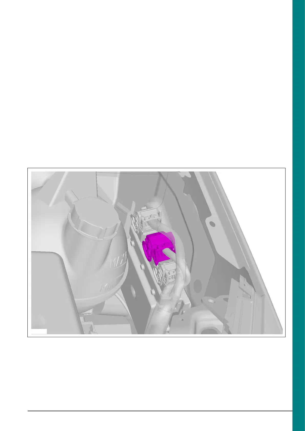
In the engine compartment there are three
connectors on the left hand side (viewed from
driving direction). On left hand drive vehicles, the
three connectors are covered with a plastic
shield that can be easily disassembled. On right
hand drive vehicles there is a special metal
security shield fixed with a shear bolt (part
number 6M5Y-12B539-A*). The vehicle speed
signal is available on pin K1 of the middle (brown)
connector, C2 – see Figure E84720 (Additional
Vehicle Signal / Features). This provides a square
wave-form (50% duty cycle) signal, where a
frequency of 138Hz equates to 100km/h.
Note:-
•
A hard-wired vehicle speed signal is only
available on diesel engine vehicles.
•
Vehicle speed is derived from one of two
sources, the wheel speed sensor (for vehicles
with ABS etc.) or the vehicle speed signal – in
both cases, these are un-calibrated signals.
According to transmission, drive-line and other
vehicle parameters that are set, the
Powertrain Control Module generates a CAN
message of vehicle speed for all vehicle types.
There is No hard-wired vehicle speed signal
on gasoline (petrol) vehicles.
•
There is No automated shift transmission for
V4347/8 (there are no plans to introduce this
later in the program).
•
VMT6 transmissions will not support fitment
of a vehicle speed sensor.
Connector Position for Vehicle Speed Signal in the Engine Compartment
In order to avoid electrical issues due to leakage,
and to ensure connector compatibility, a
pre-crimped wire and terminal, available as part
of a wiring accessory kit, should be used (kit part
number KT6C1V-14A411-J*). For further
information see 'Adding Connectors, Terminals
and Wiring' in this manual.
FordTransit 2006.5 (April 2006–)
Date of Publication: 12/2006
4 Electrical
131

 Loading...