In this example, no more than 3000 W may be fed into the grid at the grid feed-in
point. However, any loads that are located between the inverter and the grid feed-in
point can be supplied by additional power from the inverter. These loads are also com-
pensated as required.
Dynamic power
regulation with
several inverters
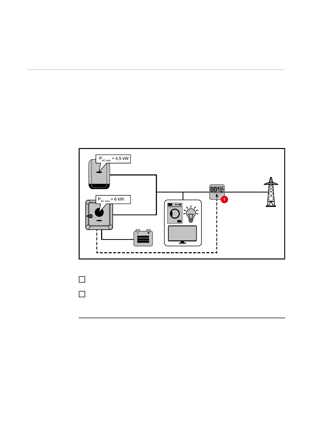
Example 1: Fronius SnapINverter ≤ Fronius Primo GEN24
Only one primary meter is required for the Fronius Primo GEN24 inverter.
The power values shown are an example. Inverter configurations with power values
other than those shown in the example are possible, taking into account the criteria for
this example.
IMPORTANT!
Zero feed-in is not possible when using 2 inverters.
Settings on the Fronius Primo GEN24 inverter website:
1
Configure the primary meter at the feed-in point in the "Device configuration" →
"Components" menu area.
2
Activate the limit for the entire system in the "Safety and grid regulations" → "Export
limitation" menu area. Enter the DC nominal output of the entire PV system in the
"Total DC system power" input field. Enter the percentage value (50%, 60% or 70%)
in the "Maximum permitted feed-in power of the entire system" input field.
Example 2a: Fronius SnapINverter > Fronius Primo GEN24
Two primary meters are required for the inverters.
The power values shown are an example. Inverter configurations with power values
other than those shown in the example are possible, taking into account the criteria for
this example.
IMPORTANT!
With two primary meters at the feed-in point without a secondary meter, Fronius SnapIN-
verter and Fronius Primo GEN24 inverters cannot be displayed as a combined PV sys-
tem in Solar.web. Two individual PV systems must be created in Solar.web.
106

 Loading...