Modbus 0 (MB0) switch
Switches the terminating resistor for
Modbus 0 (MB0) on/off.
Position 1: Terminating resistor on
(factory setting)
Position 0: Terminating resistor off
Modbus 1 (MB1) switch
Switches the terminating resistor for
Modbus 1 (MB1) on/off.
Position 1: Terminating resistor on
(factory setting)
Position 0: Terminating resistor off
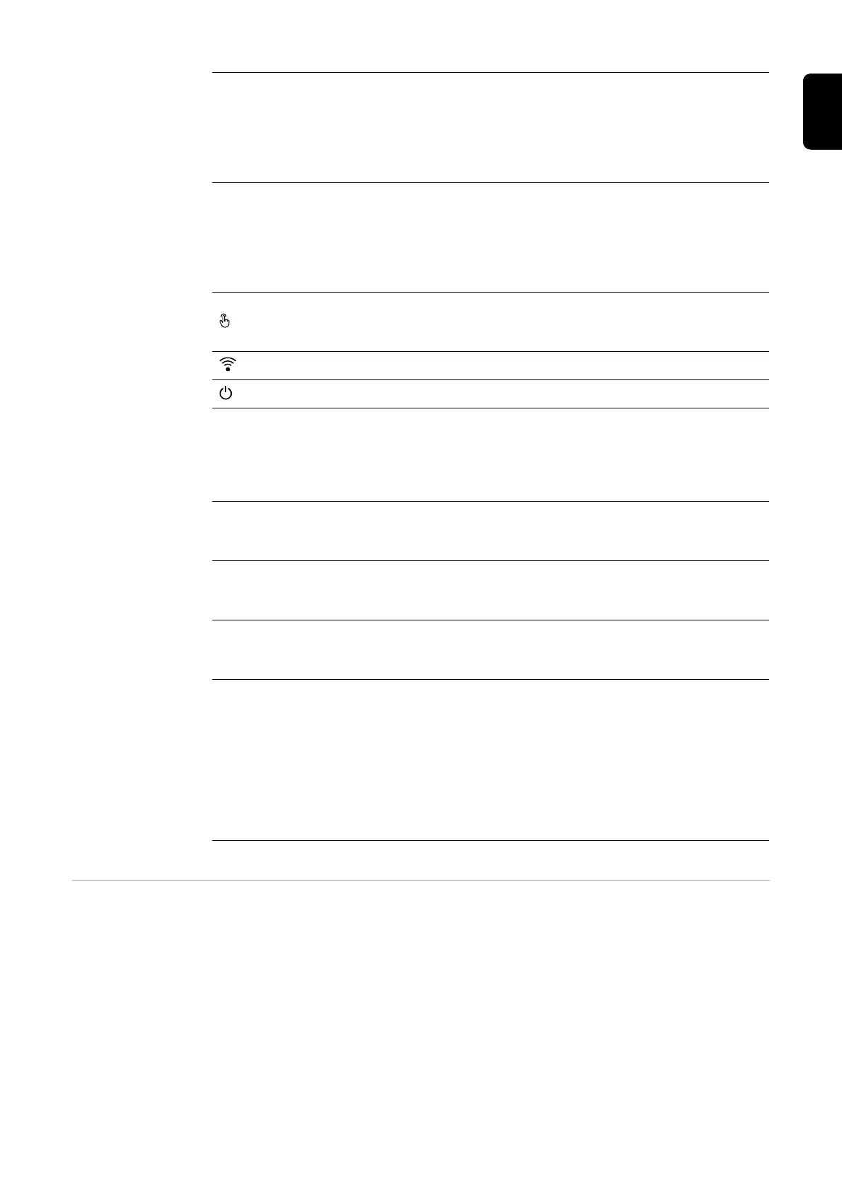
Optical sensor
To operate the inverter. See chapter
Button functions and LED status
indicator on page 87.
Communication LED
Indicates the inverter connection status.
Operating status LED
Indicates the inverter operating status.
LAN 1
Ethernet connection for data communic-
ation (e.g. WLAN router, home network
or for commissioning with a laptop, see
chapter Installation using the web
browser on page 89).
LAN 2
Ethernet connection only for data com-
munication from inverter to inverter (cur-
rently unavailable).
WSD terminal
Push-in terminal for the WSD installa-
tion. See chapter WSD (wired shut-
down) on page 25.
USB Power supply max. 1 A at 5 V. Software
updates and data recording via USB is
not possible.
IOs terminal
Push-in terminal for digital inputs/
outputs. See chapter Permitted cables
for the data communication area on
page 55.
The designations (RG0, CL0, 1/5, 2/6,
3/7, 4/8) on the terminal refer to the
Demand Response Mode function, see
chapter Functions andI/Os on page
94.
Internal schem-
atic connection
diagram of the
IOs
On the V+/GND pin, it is possible to feed in a voltage of around 12.5 - 24 V (+ max. 20%)
with an external power supply. The outputs IO 0 - 5 can then be operated with the
external voltage. A maximum of 1 A can be drawn per output, with a maximum of 3 A
allowed in total. The fuse protection must be located externally.
29
EN

 Loading...