EasyManuals Logo

Fronius Primo GEN24 3.0 Plus User Manual

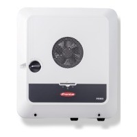
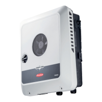
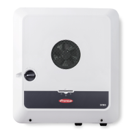
Fronius Primo GEN24 3.0 Plus
160 pages
To Next Page IconTo Next Page
To Previous Page IconTo Previous Page
Page #42 background imageLoading...
Page #42 background image
Transitioning
from backup
power mode to
feeding energy
into the grid
1. The inverter is operating in backup power mode. The contactors K1 and K2 to the
public grid are open.
2. Public grid available again.
3. The Fronius Smart Meter monitors the grid parameters on the public grid and
passes this information to the inverter.
4. The stability of the returned public grid is determined by checking the measured val-
ues of the Fronius Smart Meter.
5. On the basis of adjustments that have been carried out, the inverter ends backup
power mode and disconnects the outputs.
6. The inverter deactivates K3. Power is restored to contactors K1, K2, K4 and K5.
7. All circuits are reconnected to the public grid and are supplied by the grid. The
inverter does not feed anything into the grid at this time.
8. The inverter can start feeding energy into the grid again after performing the grid
checks required by the relevant standard.
42

Table of Contents

Questions and Answers:

Question and Answer IconNeed help?

Do you have a question about the Fronius Primo GEN24 3.0 Plus and is the answer not in the manual?

Fronius Primo GEN24 3.0 Plus Specifications

General IconGeneral
Max. input current12 A
Max. input voltage1000 V
Protection classIP66
Max. output current13 A
THD< 3%
Max. input current (DC)12 A
Number of MPP trackers2
Max. DC short-circuit current18 A
AC Output Frequency50/60 Hz
AC nominal output3000 W
Max. apparent AC power3000 VA
AC nominal voltage230 V
Operating Temperature Range-25 to +60 °C
CoolingActive cooling
Maximum Input Power4, 500 W
Warranty5 years

Related product manuals