EasyManua.ls Logo

Fronius Primo GEN24 3.0 Plus User Manual

Fronius Primo GEN24 3.0 Plus
160 pages
To Next Page IconTo Next Page
To Previous Page IconTo Previous Page
Page #28 background imageLoading...
Page #28 background image
DC disconnector The DC disconnector has three switch set-
tings:
(1) Locked/off (turned to the left)
(2) Off
(3) On
IMPORTANT!
In switch settings (1) and (3), a conven-
tional padlock can be used to secure the
inverter against being switched on/off.
- The national guidelines must be com-
plied with in this respect.
Data communica-
tion area
WSD
10
Modbus
GND V+
M0- M0+
SHIELD SHIELD
M1- M1+
GND V+
RS485 (0/1) Fronius Smart Meter,
Ohmpilot, Battery (only GEN24),
Sunspec, Interface, ...
LAN 2
LAN 1
USB
(1A,5V)
Modbus 1
10
Modbus 0
10
Terminating resistor
LED
LED
WSD
IN+IN-
OUT+OUT-
WSD > wired disconnection
of grid feed-in
Factory default
Terminating resistor
Only inverter
to inverter
communication
IP: 169.254.0.180
IOs
GND
GND
V+
V+
IO1 IO0
IO3 IO2
IO5* IO4*
IN7* IN6*
IN9*
IN8*
IN11 IN10
Load Management,
Demand Respone Mode (DRM)*,
Back-up power, IO control, ...
IO4 = RG0 (Ref GEN/0)
IO5 = CL0 (COM LOAD/0)
IN6 = 1/5
IN7 = 2/6
IN8 = 3/7
IN9 = 4/8
I/Os
* Demand Response Mode (DRM)
Frequency band: channel 1-11(2412-2462 MHz)
Radio-frequency power: <100 mW (<20 dBm)
Technical Data (WLAN)
IP WLAN: 192.168.250.181 | Password: 12345678
Modbus terminal
Push-in terminal for the installation of
Modbus 0, Modbus 1, 12 V and GND
(ground).
The data connection to the connected
components is established via the Mod-
bus terminal. The inputs M0 and M1
can be selected for this purpose.
Max. 4 Modbus participants per input,
see chapter Modbus participants on
page 80.
WSD (wired shutdown) switch
Defines the inverter as a WSD master or
WSD slave.
Position 1: WSD master
Position 0: WSD slave
28

Table of Contents

Question and Answer IconNeed help?

Do you have a question about the Fronius Primo GEN24 3.0 Plus and is the answer not in the manual?

Fronius Primo GEN24 3.0 Plus Specifications

General IconGeneral
Max. input current12 A
Max. input voltage1000 V
Protection classIP66
Max. output current13 A
THD< 3%
Max. input current (DC)12 A
Number of MPP trackers2
Max. DC short-circuit current18 A
AC Output Frequency50/60 Hz
AC nominal output3000 W
Max. apparent AC power3000 VA
AC nominal voltage230 V
Operating Temperature Range-25 to +60 °C
CoolingActive cooling
Maximum Input Power4, 500 W
Warranty5 years

Summary

Fronius Primo GEN24 Operating Instructions

Safety Rules and Warnings

Covers general safety, personnel, environmental considerations, and warning symbol explanations.

Backup Power Functionality Overview

Introduces backup power features and factors influencing its performance.

Protective Earthing (PE) Requirements

Explains the purpose and installation requirements for protective earthing.

Device Operation and System Modes

General Information and Device Concept

Describes the inverter's function, components, and intended use.

Operating Modes Explained

Details various operating modes and explains associated symbols and energy flow.

Energy Saving Mode Operation

Explains the energy saving mode, including switch-off/on conditions and indications.

Installation Procedures

Installation Location and Mounting

Guides on choosing the location, mounting bracket installation, and inverter attachment.

Electrical Connection Prerequisites

Specifies permitted cables, cross-sections, and fuse protection for connections.

Connecting to Grid, PV, and Battery

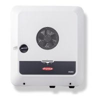
Provides procedures and safety for connecting the inverter to the public grid, PV modules, and battery.

Backup Power Variants Installation

Covers installation, safety, and testing for PV Point and Full Backup power modes.

System Configuration and Settings

User and Device Configuration

Details user login, language selection, and component configuration.

Energy Management and Power Control

Explains self-consumption optimization, PV power reduction, and load management settings.

Communication and Network Setup

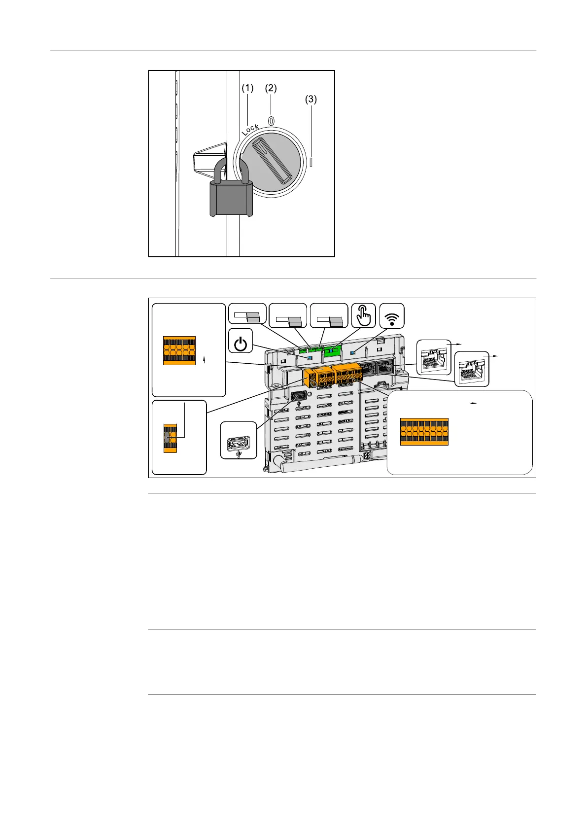
Guides on configuring LAN, WLAN, Modbus, and other communication interfaces.

Grid Compliance and Feed-in Limitations

Covers feed-in limitations, dynamic power regulation, and safety/grid requirements.

Technical Data, Diagrams, and Dimensions

Inverter Technical Specifications

Lists detailed technical specifications for DC inputs, AC outputs, general data, and protection devices.

Circuit Diagrams for System Configurations

Illustrates circuit diagrams for various backup power and system configurations.

Inverter Dimensions

Displays the physical dimensions of the inverter.

Maintenance, Troubleshooting, and Warranty

Care and Maintenance Procedures

Provides guidelines for cleaning, maintenance, and safety during service.

Status Codes and Troubleshooting

Details status codes, their causes, and troubleshooting steps for common issues.

Guarantee Provisions

Explains warranty terms and product registration.

Related product manuals