EasyManuals Logo

Fronius Primo GEN24 3.0 Plus User Manual

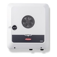
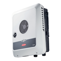
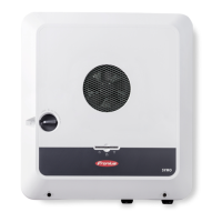
Fronius Primo GEN24 3.0 Plus
160 pages
To Next Page IconTo Next Page
To Previous Page IconTo Previous Page
Page #113 background imageLoading...
Page #113 background image
Connection dia-
gram - 2 relays
The ripple control signal receiver and the I/Os terminal of the inverter can be connected
to one another in accordance with the connection diagram.
If the distance between the inverter and the ripple control signal receiver exceeds 10 m,
at least a CAT 5 cable is recommended and the shield must be connected at one end to
the push-in terminal of the data communication area (SHIELD).
(1) Ripple control signal receiver with 2 relays, for effective power limitation.
(2) I/Os of the data communication area.
Use the preconfigured file for 2-relay mode:
1
Download the file (.fpc) under 2-relay mode onto the end device.
2
Upload the file (.fpc) in the "I/O Power Management" menu using the "Import" button.
3
Click on the “Save” button.
The settings for 2-relay mode are stored.
113
EN

Table of Contents

Questions and Answers:

Question and Answer IconNeed help?

Do you have a question about the Fronius Primo GEN24 3.0 Plus and is the answer not in the manual?

Fronius Primo GEN24 3.0 Plus Specifications

General IconGeneral
Max. input current12 A
Max. input voltage1000 V
Protection classIP66
Max. output current13 A
THD< 3%
Max. input current (DC)12 A
Number of MPP trackers2
Max. DC short-circuit current18 A
AC Output Frequency50/60 Hz
AC nominal output3000 W
Max. apparent AC power3000 VA
AC nominal voltage230 V
Operating Temperature Range-25 to +60 °C
CoolingActive cooling
Maximum Input Power4, 500 W
Warranty5 years

Related product manuals