Closing and commissioning the inverter
Closing the
inverter's con-
nection area/
housing cover,
and commission-
ing
NOTE!
The housing cover is fitted with a lock for safety reasons, which allows the hous-
ing cover on the inverter to be pivoted only when the DC disconnector is switched
off.
▶
Only clip and pivot the housing cover onto the inverter when the DC disconnector
is switched off.
▶
Do not use excessive force to clip in and pivot the housing cover.
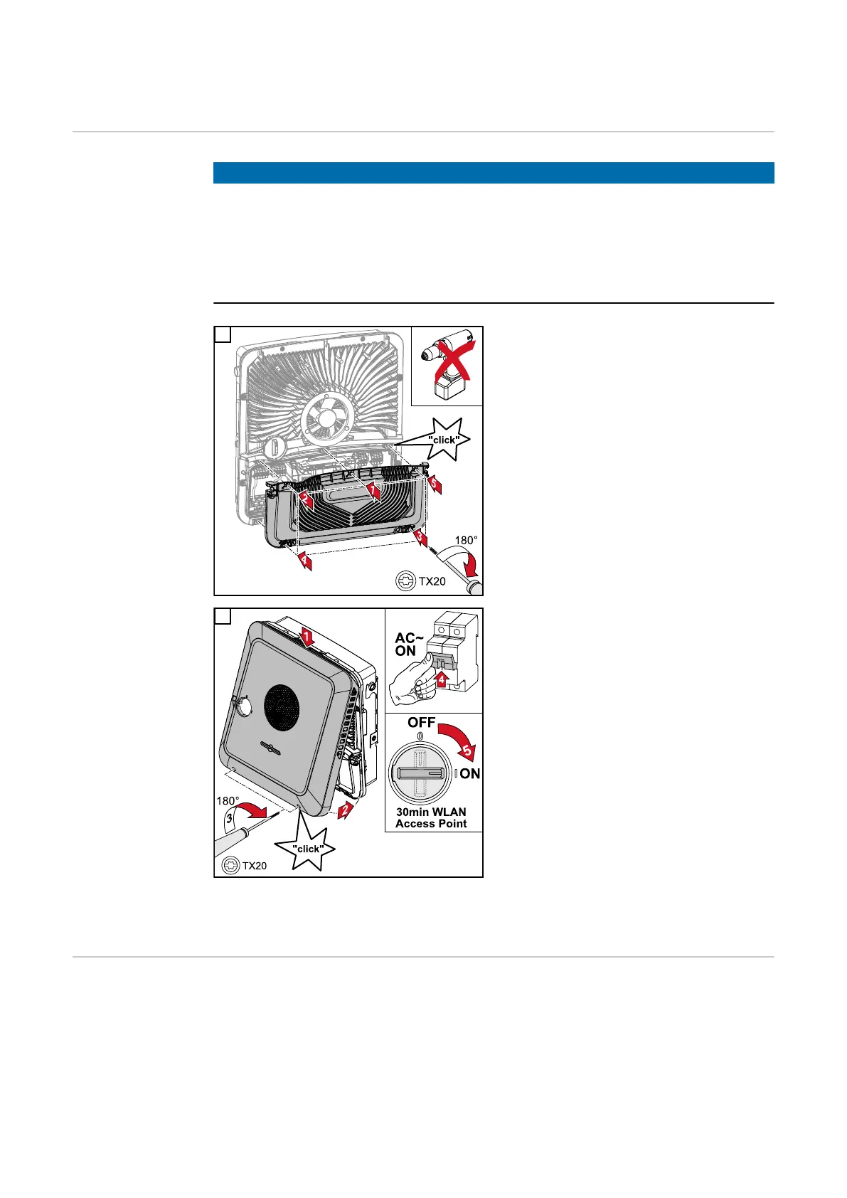
1
Place the cover on the connection area.
Tighten the five screws by rotating them
180° to the right in the indicated order
using a screwdriver (TX20).
2
Clip the housing cover onto the inverter
from above.
Press on the lower part of the housing
cover and tighten the two screws 180° to
the right using a Torx screwdriver (TX20).
Turn on the automatic circuit breaker.
Turn the DC disconnector to the "On"
switch position. For systems with a battery,
observe the switch-on sequence according
to chapter Suitable battery on page 23.
IMPORTANT! The WLAN access point
(AP) will only then be activated by the DC
disconnector if the inverter is not con-
figured. Open WLAN access point with the
optical sensor, see chapter Button func-
tions and LED status indicator on page
87
Starting the
inverter for the
first time
When using the inverter for the first time, various setup settings must be configured.
If the setup process is cancelled before the process is complete, any data that has been
input up to this point is lost and the start screen with the installation wizard is shown
again. If the process is interrupted, such as in the event of a power outage, the data is
saved. Commissioning may be continued from the point at which the process was inter-
rupted once the power supply has been restored. If the setup was interrupted, the
86

 Loading...