EasyManuals Logo

Fronius Primo GEN24 3.0 Plus User Manual

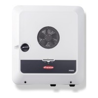
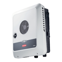
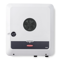
Fronius Primo GEN24 3.0 Plus
160 pages
To Next Page IconTo Next Page
To Previous Page IconTo Previous Page
Page #27 background imageLoading...
Page #27 background image
(9) Connection area divider
(10) 10 x DC cable glands
(11) Optional cable gland (M16)
(12) Optional cable gland (M16 - M20)
(13) Optional cable gland (M16 - M32)
(14) Optional cable gland (M16 - M25)
Connection area
divider
The connection area divider separates the high-voltage conductors (DC and AC) from
the signal lines. To make it easier to reach the connection area, the divider can be
removed for the connection work, and must be re-inserted.
(1) Integrated cable duct
(2) Recesses for removing the con-
nection area divider
(3) Snap tabs for locking/unlocking
(4) Defined breaking point for the Dat-
com connection
The integrated cable duct (1) allows for the
lines to be laid from one area of the
inverter to the other. As a result, multiple
inverters can be easily installed next to
each other.
Ground electrode
terminal
The ground electrode terminal Allows
additional components to be earthed, such
as:
- AC cable
- Module mounting system
- Ground rod
27
EN

Table of Contents

Questions and Answers:

Question and Answer IconNeed help?

Do you have a question about the Fronius Primo GEN24 3.0 Plus and is the answer not in the manual?

Fronius Primo GEN24 3.0 Plus Specifications

General IconGeneral
Max. input current12 A
Max. input voltage1000 V
Protection classIP66
Max. output current13 A
THD< 3%
Max. input current (DC)12 A
Number of MPP trackers2
Max. DC short-circuit current18 A
AC Output Frequency50/60 Hz
AC nominal output3000 W
Max. apparent AC power3000 VA
AC nominal voltage230 V
Operating Temperature Range-25 to +60 °C
CoolingActive cooling
Maximum Input Power4, 500 W
Warranty5 years

Related product manuals