• Automatic
freeze
protection
- Whenever power is sup-
plied
to
the
unit
and
the master switch is
in
the
ON
posi-
tion, automatic freeze protection is active.
If
the
unit
senses
temperature below
40°F,
the fan motor and elec-
tric
strip heat are turned on. Freeze protection can
be
turned
off,
if
required.
• Random
restart
delay
To
help eliminate power surges
after
a power outage, the
unit
is equipped
with
a
two
to
four minute random restart delay feature. Whenever the
unit
is plugged in
with
the master switch turned on and
the mode switch set
in
the cool
or
heat mode, a random
restart
will
occur. A random restart condition can
be
avoided by setting the mode switch in the fan only or
off
poSition before applying power
to
the unit.
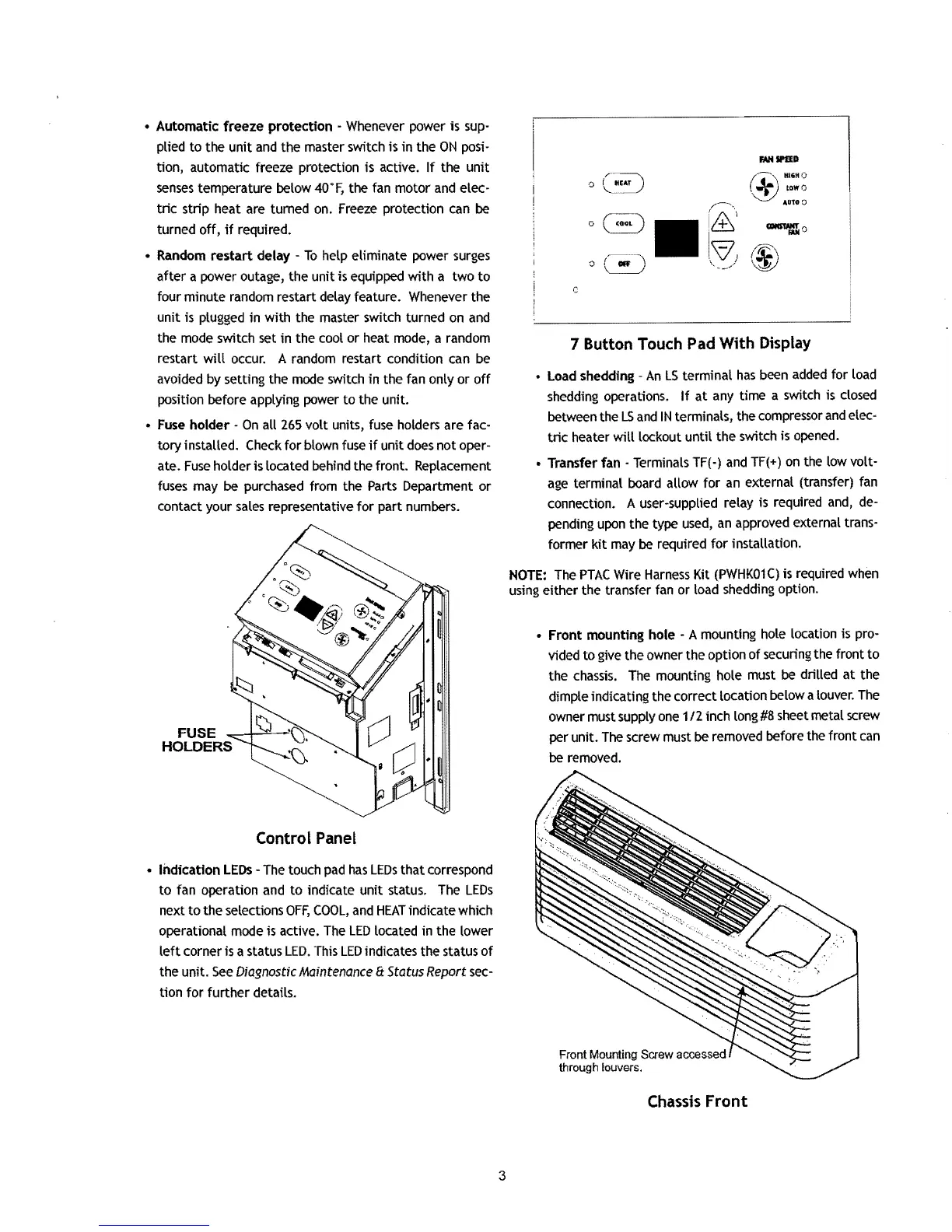
• Fuse
holder
-
On
all
265
volt
units, fuse holders are fac-
tory
installed. Check
for
blown fuse
if
unit
does
not
oper-
ate.
Fuse
holder is located behind the front. Replacement
fuses may be purchased from the Parts Department
or
contact your sales representative
for
part numbers.
FUSE
HOLDERS
Control Panel
•
Indication
LEOs
- The touch pad
has
LEOs
that
correspond
to
fan operation and
to
indicate unit status. The
LEOs
next
to
the selections
OFF,
COOL,
and
HEAT
indicate which
operational mode is active. The
LED
located in the lower
left
corner is a status
LED.
This
LED
indicates the status
of
the unit.
See
Diagnostic Maintenance
8:
Status Report sec-
tion
for
further
details.
__
D
(~\
.16.<)
\.~
lOWO
AU100
c
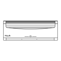
7 Button Touch Pad With Display
• Load shedding -
An
LS
terminal
has
been added for load
shedding operations.
If
at
any time a switch is closed
between the
LS
and
IN
terminals, the compressor
and
elec-
tric
heater
will
lockout
until
the
switch is opened.
• Transfer fan - Terminals TF(-)
and
TF(+)
on
the low volt-
age
terminal board allow
for
an external (transfer) fan
connection. A user-supplied relay is required and, de-
pending upon the type used,
an
approved external trans-
former
kit
may
be
required
for
installation.
NOTE:
The
PTAC
Wire
Harness
Kit
(PWHK01C)
is required when
using
either
the transfer fan or load shedding option.
•
Front
mounting hole - A mounting hole location is pro-
vided to give the owner the option
of
securing the front
to
the
chassis.
The mounting hole must
be
drilled
at
the
dimple indicating the correct location below a louver. The
owner must supply one
112
inch long
#8
sheet metal screw
per unit. The screw must
be
removed before the front
can
be
removed.
Front Mounting Screw accessed
through louvers.
Chassis
Front
3

 Loading...