INSTALLATION
INSTRUCTIONS
To
ensure that the unit operates safely and efficiently,
it
must
be installed, operated and maintained according
to
these instal-
lation and operating instructions and all local codes and ordi-
nances or, in their absence, with the latest edition of
the
National Electric Code. The proper installation of this unit is
described in the following sections.
Following
the steps
in
the
order presented should ensure proper installation.
A
WARNING
~I
HIGH
VOLTAGE
•
DISCONNECT
ALL
POWER BEFORE SERVICING.
fi
MULTIPLE
POWER SOURCES
MAY
BE PRESENT. FAILURE
TO DO SO
MAY
CAUSE
PROPERlY
DAMAGE, PERSONAL
INJURY OR DEATH.
Do NOT SERVICE THIS UNIT WITHOUT FIRST
ENSURING THAT:
THE
ELECTRICAL ACCESSORIES ARE INSTALLED
ONLY
IN THE
PRE-DRILLED MOUNTING HOLES.
THE
ELECTRICAL WIRING IS NOT INSTALLED AND DOES NOT HANG
BELOW
THE PRE-DRILLED MOUNTING HOLE OR LIE IN THE UNIT
BASE
PAN.
SLEEVE
STIFFEN
ER
AND
REAR
CLOSURE
PAN
EL
REMOVAL
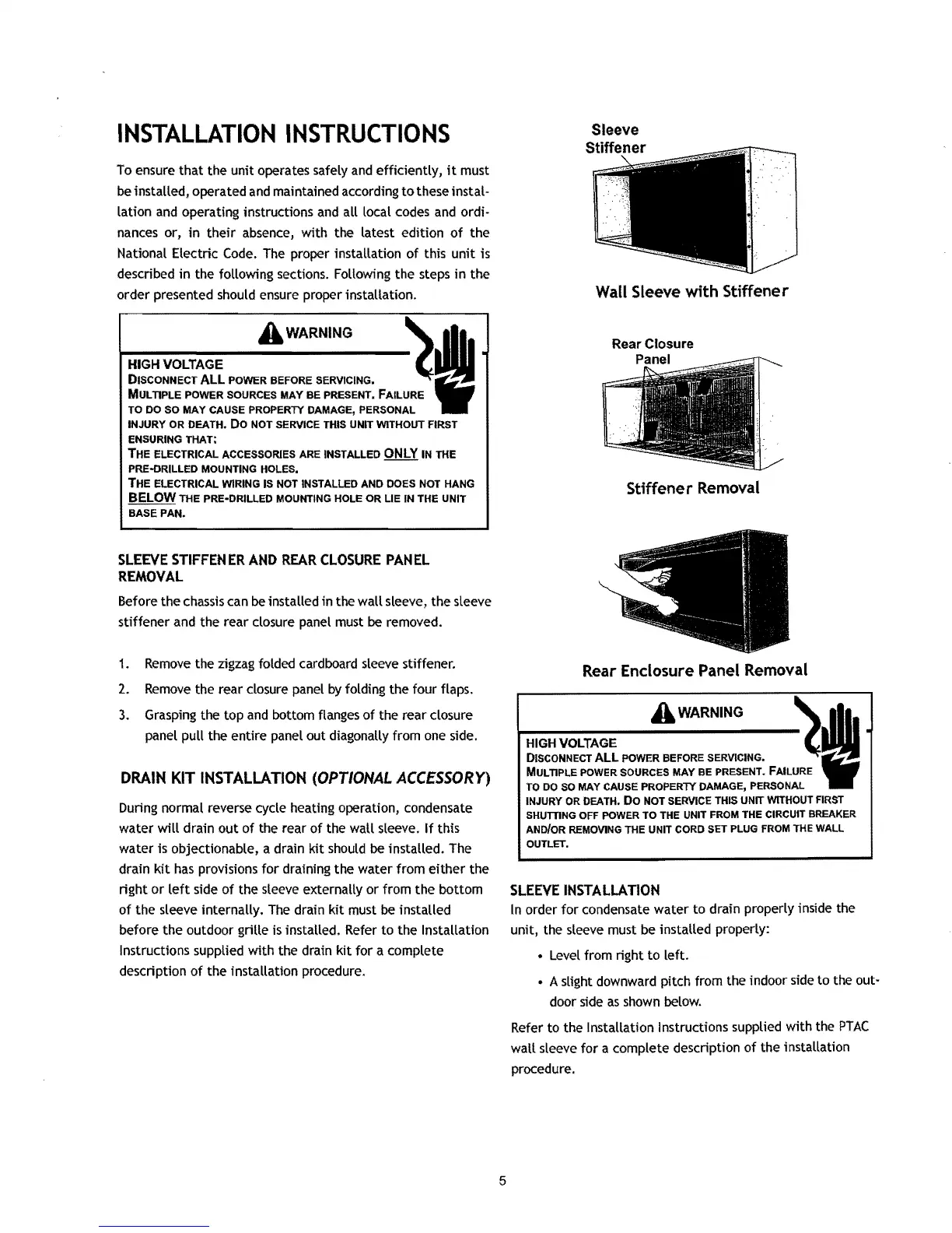
Before
the
chassis can be installed
in
the wall sleeve,
the
sleeve
stiffener and the rear closure panel must be removed.
1.
Remove
the zigzag folded cardboard sleeve stiffener.
2.
Remove
the rear closure panel
by
folding the four flaps.
3.
Grasping the top and bottom flanges of the rear closure
panel pull the entire panel out diagonally from one side.
DRAIN
KIT
INSTALLATION
(OPTIONAL
ACCESSORY)
During
normal reverse cycle heating operation, condensate
water
will
drain
out
of the rear of the wall sleeve.
If
this
water is objectionable, a drain
kit
should be installed. The
drain kit has provisions for draining the water from either the
right
or
left side of the sleeve externally or from
the
bottom
of the sleeve internally.
The
drain kit must be installed
before the outdoor grille
is
installed. Refer to the Installation
Instructions supplied with the drain kit for a complete
deSCription of
the
installation procedure.
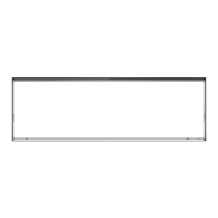
Wall Sleeve
with
Stiffener
Stiffener
Removal
Rear Enclosure Panel Removal
A
WARNING
~I
~---------------------
.
HIGH
VOLTAGE
DISCONNECT
ALL
POWER BEFORE SERVICING.
Ii
MULTIPLE
POWER
SOURCES MAY BE PRESENT. FAILURE
TO
DO
SO
MAY CAUSE
PROPERlY
DAMAGE, PERSONAL
INJURY OR DEATH.
Do
NOT SERVICE THIS UNIT WITHOUT FIRST
SHumNG
OFF POWER TO THE UNIT
FROM
THE CIRCUIT BREAKER
AND/OR
REMOVING
THE UNIT CORD SET PLUG
FROM
THE WALL
OUTLET.
SLEEVE
INSTALLATION
In
order for condensate water to drain properly inside the
unit, the sleeve must be installed properly:
•
Level
from right to left.
• A slight downward pitch from the indoor side to the out-
door side as shown below.
Refer to the
Installation Instructions supplied with the
PTAC
wall sleeve for a complete description of the installation
procedure.
5

 Loading...