Table 5
shows
the maximum wire length
and
corresponding
gage
size
for installation
of
a remote thermostat.
#22 600ft
#20 900ft
#18 1500ft
#16 2000ft
Table 5 - Maximum Wire Length for Remote
Control Connection
A
WARNING
~I
HIGH
VOLTAGE
DISCONNECT
ALL
POWER
BEFORE
CLEANING
THIS
UNIT.
fi
MULTIPLE
POWER
SOURCES
MAY
BE
PRESENT. FAILURE
TO
00
SO
MAY
CAUSE
PROPERTY
DAMAGE, PERSONAL
INJURY
OR
DEATH.
MAINTENANCE
AND
CLEANING
A
WARNING
HIGH
VOLTAGE
To
AVOID
PROPERTY
DAMAGE, PERSONAL INJURY
OR
DEATH
DUE
TO
ELECTRICAL
SHOCK,
CLEAN AIR FILTERS
AND
COILS
REGULARLY. CLOGGED
OR
SEVERELY
RESTRICTED
FILTERS
OR
COIlS
REDUCE
AIRFLOW,
WHICH
CAN
CAUSE
DRASTIC
EFFICIENCY
LOSS
AS
WELL
AS
SEVERE
COMPONENT
DAMAGE
TO
COMPRESSORS,
ELECTRIC HEATER
OR
FAN
MOTOR.
IN
EXTREME
CASES, CLOGGED FILTERS AND/OR
COILS
MAY
CREATE
A
FIRE
HAZARD
AND WILL
VOID
THE
WARRANTY
A
WARNING
SOME
LOCAL
CONDITIONS
AND
ENVIRONMENTS
CAN
CAUSE
FUNGI
AND
OTHER
MATERIAL
TO
GROW
INSIDE
THE
PTAC
UNIT.
THIS
MATERIAL
WHEN
DRIED,
AS
WELL
AS
OTHER
FOREIGN
MATERIAL,
SIMILAR
TO
DRYER
LINT
IN
YOUR
CLOTHES
DRYER,
ARE
FIRE
HAZARDS.
BE
SURE
TO
THOROUGHLY
CHECK
AND
LEAN
THE
UNIT'S
COILS,
BLOWER
WHEEL
AND
BASEPAN
PER
THE
INSTRUCTIONS
CONTAINED
IN
THIS
MANUAL
MONTHLY
MAINTENANCE
AND
CLEANING
Intake
Air
Filters
To properly maintain the operational performance
of
your
PTAC
unit,
it
is
extremely
important that the
inlet
air filters
be
cleaned
once
per month or more often
if
operated in dusty or
dirty
locations or conditions. The intake air filters are con·
structed
of
durable polypropylene. The
"air
intake"
air filters
can
be
easily inserted
into
the cabinet
front
using the cabinet
filter
guides. Before cleaning the intake
filter,
turn the unit
off
by
setting the mode switch to the
OFF
position.
Filter
should
be
cleaned
as
required.
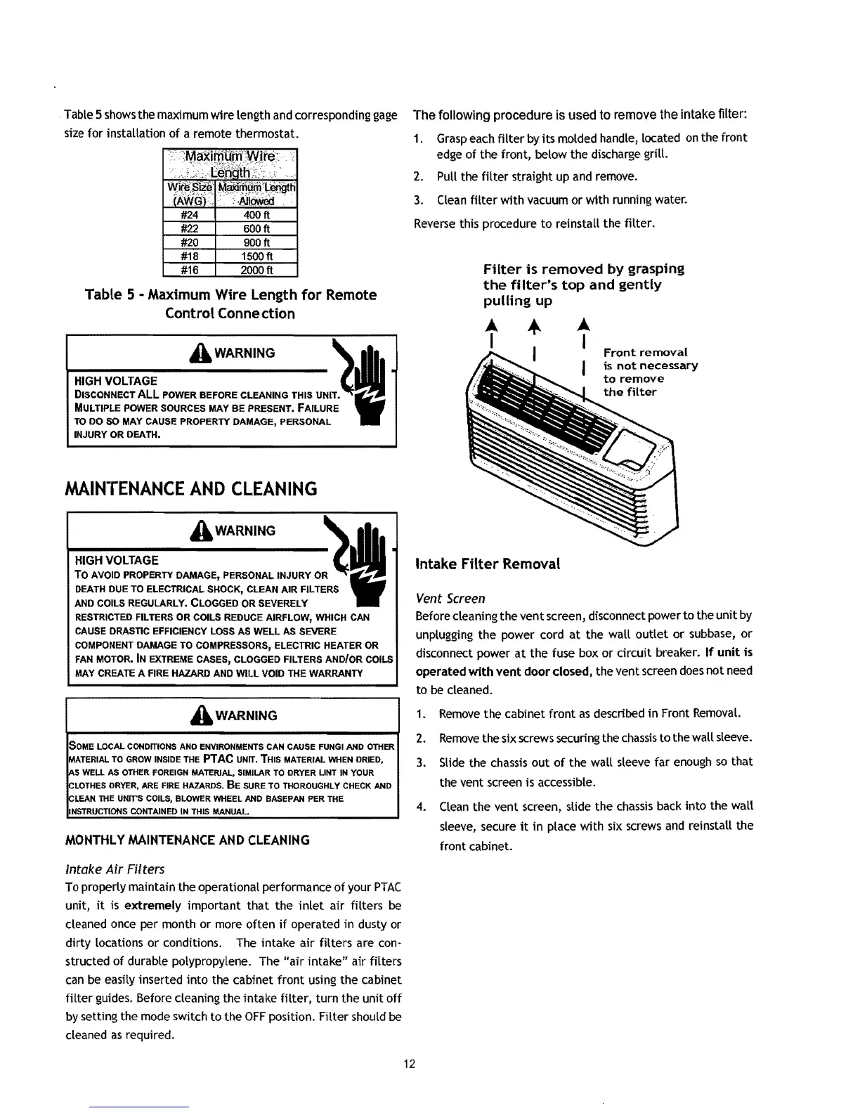
The following procedure is used to remove the intake filter:
1.
Grasp
each
filter
by
its molded handle, located
on
the front
edge
of
the front, below the discharge grill.
2.
Pull the
filter
straight up
and
remove.
3.
Clean
filter
with vacuum or with running water.
Reverse
this procedure
to
reinstall the
filter.
Filter
is
removed
by grasping
the
filter's
top
and
gently
pulling
up
..
..
I
I
Front
removal
is
not
necessary
to
remove
the
filter
Intake Filter Removal
Vent
Screen
Before cleaning the vent screen, disconnect power to the
unit
by
unplugging the power cord
at
the wall
outlet
or
subbase,
or
disconnect power
at
the fuse box
or
drcuit
breaker.
If
unit
is
operated
with
vent
door
closed, the vent screen
does
not need
to
be
cleaned.
1.
Remove
the cabinet front
as
described
in
Front
RemovaL
2.
Remove
the six screws securing the
chassis
to the wall sleeve.
3.
Slide
the
chassis
out
of
the wall sleeve far
enough
so
that
the vent screen is accessible.
4.
Clean
the vent screen, slide the
chassis
back
into
the wall
sleeve, secure
it
in
place with six
screws
and
reinstall the
front cabinet.
12

 Loading...