VOLTAGE
MEASUREMENTS
Please
refer
to
the Maintenance and Cleaning section
for
the
Once
the
unit
is
properly wi red, measure
the
u
nit
supply vol tage.
Voltage must fall within the voltage utilization range given
in
Table
2.
Operating Voltage
Unit Voltage
Voltage Utilization Range
Rating
Minimum
Maximum
230/208
197
253
265
238
292
115
103.5
126.5
Table 2 - Operating Voltage
OPERATING INSTRUCTIONS
USERS
CONTROLS
A 7 button touch
key
pad, located behind the control door,
controls both temperature and operation mode.
The
key
pads
can
be
used
alone or in combination.
THERMOSTAT
SETIING
7
BUTTON
TOUCH
PAD
WITH
DISPLAY
Pressi
ng
the
COOL
thermosta t control and the up or down arrows
will
provide a cooler room temperature. Pressing the
HEAT
thermostat control and the up or down arrow
keys
will
provide
a warmer room temperature.
LCDI
OR
AFCI
POWE
R
CORD
2301208Vand
115V
units are equipped
with
LCDI
or
AFCI
power
cords and can open the electrical
circuit
to
the unit.
In
the event
the
unit
does
not
operate, check
the
reset button located
on
or
near the head
of
the power cord
as
part
of
the normal trouble-
shooting procedure.
FAN
SPEED
The
fan speed touch key
will
deliver high, low or auto fan
speed
to
circulate room air.
NOTE:
The
AUTO
selection
will
not
be
available
if
a fan
speed
is
selected
without
COOL
or Heat
selection.
Fan
Operation
HIGH
or
LOW
with
HEAT
or
COOL
mode selected
-
The
selected fan
speed
shall run
in
the selected speed.
Fan
Operation
AUTO
with
HEAT
or
COOL
mode selected - The fan
will
run
in
low
and
high speed.
The
changes
in
fan speed are
automatic.
DIAGNOSTIC
LIGHT
The green diagnostic light located
in
the lower
left
hand corner
of
the touch pad and indicates operation warnings. This
light
usually indicates
that
either the
filter
or coils need cleaning.
proper cleaning procedure.
If
this
light
is still
on
after
cleaning,
please
refer
to
the Diagnostic & Status Report section
for
assistance.
MH5PftD
f"i::
'Jrl
"I6H 0
LOWO
0
!&\
\ ,
~;
AUTO:)
0
C"~~';~')
~o
-
,
I~'
'
\~,
0
\.,£)
"
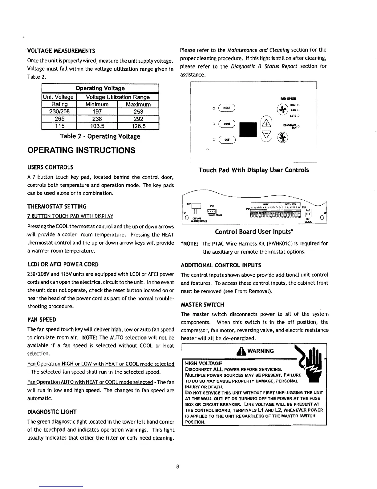
Touch
Pad
With Display User Controls
Control Board User Inputs*
*NOTE:
The
PTAC
Wire Harness Kit
(PWHK01C)
is required
for
the auxiliary
or
remote thermostat options.
ADDITIONAL
CONTROL
INPUTS
The control inputs shown above provide additional unit control
and features. To access these control inputs, the cabinet
front
must
be
removed (see Front Removal).
MASTER
SWITCH
The master switch disconnects power to all
of
the system
components.
When
this switch is in the
off
position, the
compressor, fan motor, reverSing valve, and electriC resistance
heater
will
all be de-energized.
A WARNING
~I
HIGH
VOLTAGE
•
DISCONNECT
ALL
POWER BEFORE SERVICING.
fi
MULTIPLE POWER SOURCES MAY BE PRESENT. FAILURE
TO DO
so MAY CAUSE PROPERTY DAMAGE, PERSONAL
INJURY
OR
DEATH.
Do
NOT SERVICE THIS UNIT WITHOUT FIRST UNPLUGGING THE UNIT
AT THE
WALL
OUTLET OR TURNING OFF THE POWER AT THE FUSE
BOX
OR
CIRCUIT BREAKER. LINE VOLTAGE
WILL
BE PRESENT AT
THE CONTROL BOARD, TERMINALS L
1 AND
L2,
WHENEVER POWER
IS APPLIED TO THE UNIT REGARDLESS OF THE MASTER SWITCH
POSITION.
8

 Loading...