Do
not
install
the thermostat where
it
may be
affected
by the
following:
•
Dead
spots behind doors,
in
corners
or
under cabinets
• Hot
or
cold drafts from air ducts
• Radiant heat
from
the
sun,
appliances,
or
fireplaces
• Concealed pipes and chimneys
• Unheated (uncooled) areas behind the thermostat, such
as
an
outside walls
Consult
the
instruction sheet packaged
with
the
thermostat
for
further
details on mounting and operation.
REMOTE
THERMOSTAT
OPERATION
Approved thermostats vary slightly
in
construction and,
with
few
exceptions, are operated similarly. The following operational
description pertains
to
approved nonprogrammable thermostats
that
energize G
in
Heat and Cool mode.
HEAT/OFF/COOL
Switch
•
OFF
- cooling and heating functions are defeated.
•
HEAT
- the selected room temperature is maintained by
cycling
either
in the heat pump mode
or
electric
strip
heat. A
PTH
unit
is switched from the heat pump mode
to
electric
strip
heat when the coil temperature is 20°F
or
when the heat pump cannot keep up
with
the heating load
and a
two
stage thermostat is used.
•
COOL
- the selected room temperature is maintained by
cycling the
air
conditioner.
Table 4 summarizes the
thermostat
input
combinations and the
respective
unit
functions. The following
wiring
schematic illus-
trations
show
wiring
schematics
for
heat pump and
straight
cool
units
with
electric
resistance heat, respectively.
Ulit
Function
Heat
Purrp
Thermostat
Input
Electric Heat
Thermostat
Input
R Terrrinal to: R Terrrinal to:
OFF
NONE NONE
HEAT I
Stage 1
I
Stage 2
GL*, YflN1,
B**,
0
GL*, W2
GL*YflN1,
BOO,
or GL*, W2, 0
n/a
COOL
GL*, YflN1, B**, 0
GL*, YflN1
*or GH depending
on
speed required
**If configured,
Band
0 can be used interchangeably.
Table 4 - Remote Control Inputs
NOTE:
The
PTAC
Wire Harness
Kit
(PWHK01C)
is required
for
remote thermostat options.
ADDITIONAL
NOTES:
1. For heat pump operation, a room thermostat
with
a B (heat-
ing change over) terminal
or
an
0 terminal (cooling change
over) is required. This
will
mean
that
some
"auto changeover"
thermostats cannot
be
used,
as
many
of
them
either
do
not
have a B terminal,
or
else energize the B terminal continu-
ously when in the
"auto"
position.
2.
Additional wiring should be run
for
future
changeover
to
Heat
Pump
or
thermostat options.
3.
Run
6
to
8 wires during
initial
installation.
Tape
or
cap
off
any unused wires.
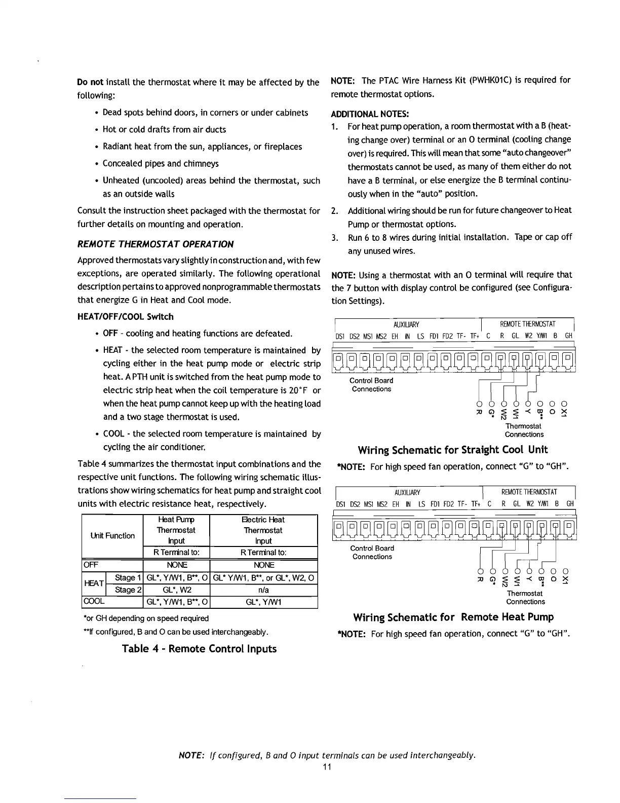
NOTE:
Using a thermostat
with
an
0 terminal
will
require
that
the 7 button
with
display control be configured
(see
Configura-
tion Settings).
AUXIUAAY
REMOTE
TffRMOSTAT
DSI
DS2
MSI
MS2
EH
IN
LS
FDI
FD2
TF-
TF+
C R
GL
W2
YNil
B
GH
~~~~~~~-~~~~,~
~~
lJV1="llJLJV~)
lJVVVV
lJiJ
Control Board
Connections
;0
Thermostat
Connections
Wiring Schematic
for
Straight Cool Unit
*NOTE: For high speed fan operation, connect
"G"
to
"GH".
AUXIUAAY
REMOTE
TffRMOSTAT
DSI
DS2
MSI
MS2
EH
IN
LS
FDI
FD2
TF-
TF+
C R
GL
W2
YNil
B
GH
Control Board
Connections
;0
o
~
Thermostat
Connections
Wiring Schematic
for
Remote Heat Pump
*NOTE: For high speed fan operation, connect
"G"
to
"GH".
NOTE:
If
configured,
Band
0
input
terminals can be used interchangeably.
11

 Loading...