REMOTE
CONTROL
INPUTS
The
C,
R,
GL,
W2,
YIW1,
BIO,
and
GH
terminaLs provide controL
inputs
for
a "manufacturer-approved" remote
waLL
mounted
thermostat. The
"B"
terminaL
can
be
configured
to
become
"0"
if
needed
see
Configuration Settings For remote controL thermo-
stat
operation, refer
to
the Remote Thermostat Operation
section.
FRONT
DESK
CONTROL
(FD1,
FD2,
EH
,
IN)
The
FD1, FD2,
EH
and
IN
terminaLs provide controL inputs
for
a
front
desk switch. Shorting
across
the
FD1
and
FD2
terminaLs
will
dis~bLe
unit
operation. The
onLy
controL function which
wiLL
remain active when these terminaLs are shorted is freeze protec-
tion.
Any switch which
wiLL
produce a short
circuit
across these
two
terminaLs
can
be
used
as
a
front
desk switch. The contact
resistance
of
the switch, when closed, must be
Less
than
200
ohms
for
the
front
desk feature
to
operate properLy.
TabLe
3
shows the maximum wire
Length
and
corresponding
gage
size
for
installation
of
a
front
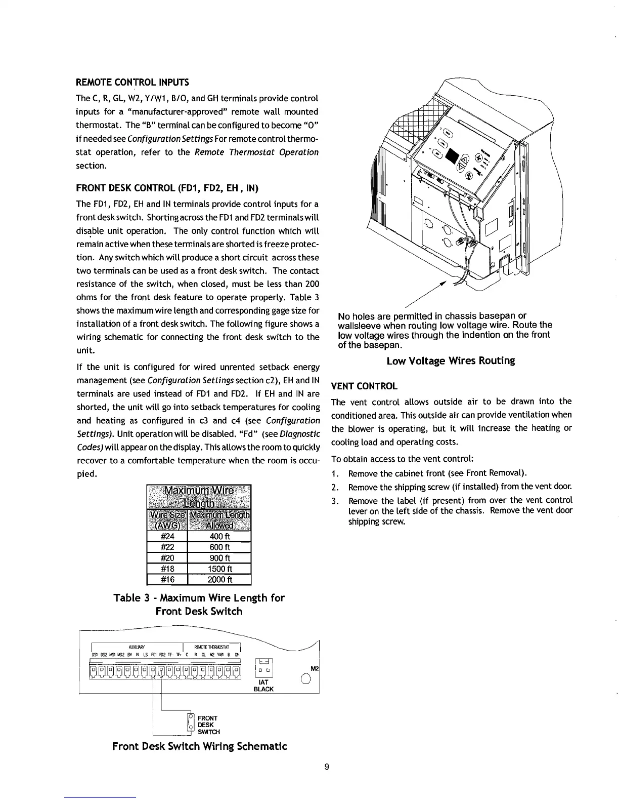
desk switch. The following figure
shows
a
wiring schematic
for
connecting the
front
desk switch
to
the
unit.
If
the
unit
is configured for wired unrented setback energy
management
(see
Configuration Settings section c2),
EH
and
IN
terminaLs are
used
instead
of
FD1
and
FD2.
If
EH
and
IN
are
shorted, the unit
wiLL
go
into
setback temperatures for
cooLing
and heating
as
configured in
c3
and
c4
(see Configuration
Settings). Unit operation
will
be
disabLed.
"Fd"
(see Diagnostic
Codes)
wiLL
appear
on
the
dispLay.
This allows the room
to
quickLy
recover
to
a comfortabLe temperature when
the
room is occu-
pied.
Table 3 - Maximum Wire Length
for
Front Desk Switch
=-
I~~~I
DS1
052
MSl
M52
EM
IN
LS
FOl
F02
TF-
IF+
C R
Gl
W2
YN/I
B
GH
iCT!
M2
8
o
IAT
BLACK
~
O,
FRONT
1d
fl
DESK
'----
__
-..J1
SWITCH
Front Desk Switch Wiring Schematic
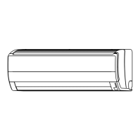
No
holes are permitted in
chassis
base
pan
or
walisleeve
when
routing
low
voltage
wire. Route
the
low
voltage
wires
through
the
indention on the front
of
the
basepan.
Low Voltage Wires Routing
VENT
CONTROL
The vent controL allows outside air
to
be drawn
into
the
conditioned area. This outside air
can
provide ventilation when
the
bLower
is operating, but
it
wiLL
increase the heating or
cooLing
Load
and
operating costs.
To
obtain
access
to
the vent controL:
1.
Remove
the cabinet front
(see
Front
RemovaL).
2.
Remove
the shipping screw
(if
instaLLed)
from the vent
door.
3.
Remove
the
LabeL
(if
present) from over the vent controL
Lever
on
the
Left
side
of
the
chassis.
Remove
the vent door
shipping
screw.
9
I

 Loading...