5.4 Block Description
5-14
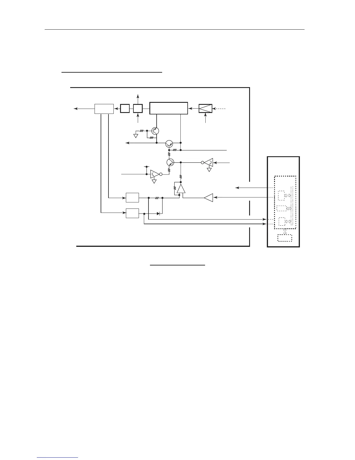
APC, R VSWR, F VSWR CIRCUIT
Fig. 5.4.7 APC Block
These power data set up by [MENU] -> SYSTEM -> TX POWER: is inputted into U4
(1/2): inversion amplifier. This voltage is a reference voltage of U4. One the other hand,
F-VSWR detected by CM coupler is detected by CR8 (half-wave detection) and is
amplified by U3 (1/2). R-VSWR is detected by CR5 and 6 (full-wave detection) and is
amplified on U3 (2/2). For example, when PWR CONT inputted into U4 (1/2) is lower
than F-VSWR voltage, U4 (1/2) output decreases. It lowers the base current of Q10 and
goes through Q2 to lower V
GG
of U1: and PA output. As a result, F-VSWR voltage
decreases as well. This voltage is the same as PWR CONT and continues until it reaches
voltage value.
F VSWR
R VSWR
U1(RA35H1516M)
U4
U4
Driver
Q1
U30
CPU
CPU
05P0773
TX/RX
05P0774
PWR CONT
Tx out
Rx
U2
(DCS3D20)
CM Coupler
F-VSWR DET
R-VSWR DET
CR6, 5
U3(2/2)
CR8
U3(1/2)
PWR CONT
UN LOCK
(From U12: PLL IC)
TEST ON
Not used
TEST ON
Not used
CR103
R52
AD
EEPROM
DA
CPU
-
+
Q11
Q8
(1/2)
Q10
Q2
Q102
T15V1
T15V
T15V
Q1:Driver Bias
Q1:Driver Bias
PA
V
DD
V
GG
(1)
(2)
(4)
(3)
LPF
T/R
SW
 Loading...