190-00709-00 Rev. A
Garmin G1000 Pilot’s Guide for the Socata TBM 850
3-7
ENGINE & AIRFRAME SYSTEMS
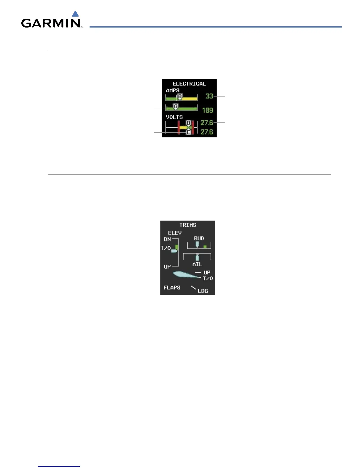
ELECTRICAL INFORMATION
Currents for the battery (pointers labeled “B”) and generator (pointer labeled “G”) and voltages for the battery
and essential bus (pointer labeled “E”) are shown along color-coded scales, with readouts to the right.
Generator
Current
Essential
Bus Voltage
Battery
Voltage
Battery
Current
Figure 3-12 Electrical Display
TRIM AND FLAP INDICATORS
Elevator, rudder, and aileron trim indications are shown along slide bar scales next to the CAS messages
in normal display mode. Flap deflection is normally displayed beneath the trim indications using a rotating
pointer. Flap positions for takeoff, landing, and up positions are labeled. In Reversionary Mode, only elevator
trim is indicated and flap position (UP, T/O, LDG) is provided as a digital readout.
Figure 3-13 Trim and Flap Indications

 Loading...