190-01553-00 GTR 200 Installation Manual
Rev. B Page 2-1
2 INSTALLATION OVERVIEW
2.1 Introduction
Careful planning and consideration of the suggestions in this section are required to achieve the desired
performance and reliability from the GTR 200. The guidance of FAA advisory circulars AC 43.13-1B and
AC 43.13-2B, where applicable, may be found useful for making retro-fit installations that comply with
FAA regulations.
2.2 Unit Configurations
2.3 Available Accessories
2.3.1 Standard Accessories
Table 2-1 Catalog Part Numbers
Model Catalog Part Number Unit Only Part Number
GTR 200 Unit Only 010-01087-00 011-02980-00
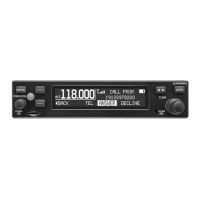
GTR 200 Standard (includes
items in Table 2-2)
010-01087-01 011-02980-00
Table 2-2 Standard Kit Accessories
Item Part Number
Installation Rack (see Figure C-2) 115-01878-00
Connector Kit (see Table 2-3) 011-03240-00
Table 2-3 Contents of Connector Kit (011-03240-00), see Figure C-2
Item Part Number Quantity
Backshell w/Hardware, 37 pin 011-00950-03 1
Connector Plate 115-01879-00 1
Ring Terminal 117-00147-01 1
Single Coax Connector Plate Adapter 125-00165-00 1
Pan Head Phillips Screw 8-32 x .312 211-60209-09 6
Flat Head Phillips Screw 4-40 x .250 211-63234-08 4
Flat Head Phillips Screw 4-40 x .375 211-63234-10 4
Split Lock Washer, size 8 212-00018-04 6
Shoulder Washer 212-00022-00 1
Flat Washer #4 212-00024-04 1
Flat Washer, Inside Diameter 0.195”, Outside Diameter 0.354” 212-20065-00 6
Alignment Pin, Shoulder #4-40 233-00087-00 1
Male/Female BNC Connector 330-00053-01 1
37 Pin D-Sub Crimp Socket Connector 330-00625-37 1
Crimp Socket Contact, Size 20, 20-24 AWG 336-00022-02 37

 Loading...