GTR 200 Installation Manual 190-01553-00
Page 3-12 Rev. B
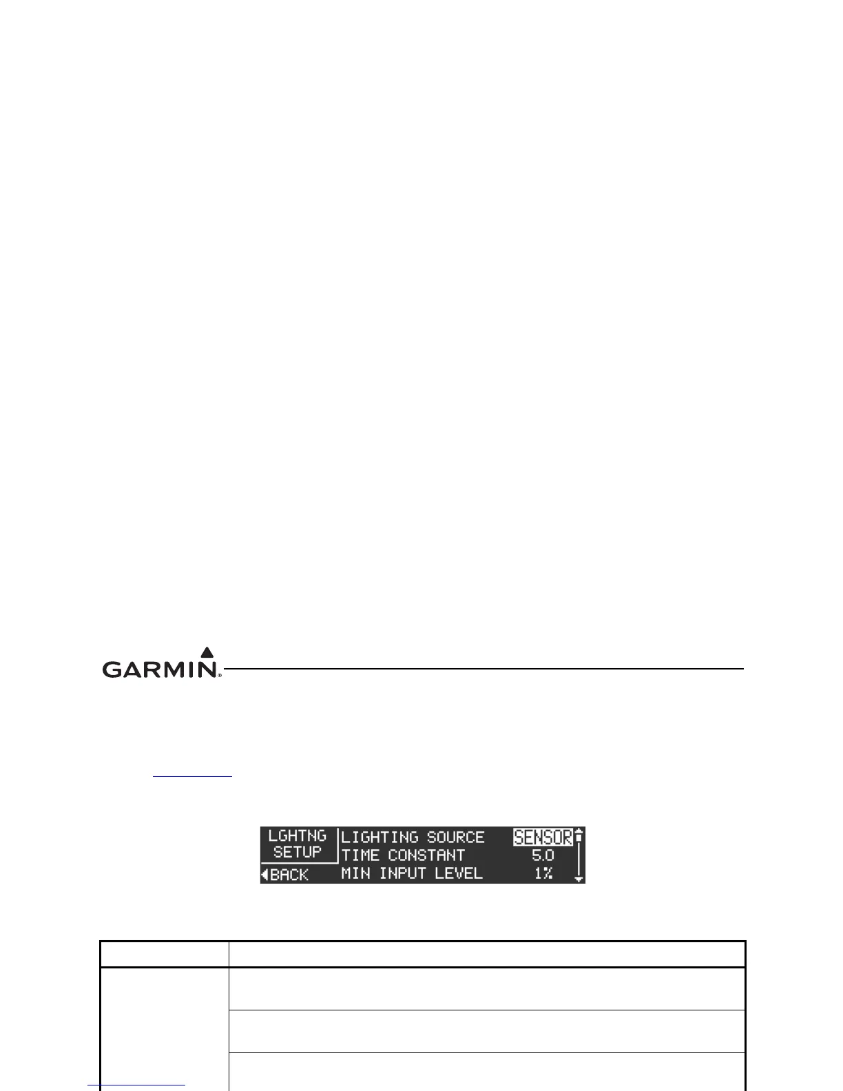
3.6.4.6 Lighting Setup Page
The Lighting Setup page (Figure 3-9) allows the installer to configure the operation of the bezel keys and
display lighting, per the options listed in Table 3-8.
Refer to Section 3.6.4
to select the Lighting Setup Page. Use the LARGE Knob to scroll through the listed
functions, then use the SMALL Knob to adjust the setting of the function. After the setting has been
changed, turn the LARGE Knob to move the cursor to another function.
Figure 3-9 Lighting Setup Page
Table 3-8 Lighting Setup Page Selections
Selection Description
LIGHTING
SOURCE
SENSOR - Bezel keys and display lighting is controlled by the light sensor
(photocell) on the front panel.
14V - Configures the lighting bus source voltage to 14V. Bezel keys and display
lighting is controlled by the input voltage (0-14 VDC) on pin 3.
28V - Configures the lighting bus source voltage to 28V. Bezel keys and display
lighting is controlled by the input voltage (0-28 VDC) on pin 3.
TIME CONSTANT
Adjusts the speed (in seconds), that the brightness level responds to changes in
the input level.
MIN INPUT
LEVEL
Sets the lower input level required to turn the backlighting on to the percentage of
brightness set by the Min Brightness setting.
MIN
BRIGHTNESS
Sets the minimum brightness of the display backlight.
MAX INPUT
LEVEL
Sets the upper input level required to turn the backlighting on to the percentage of
brightness set by the Max Brightness setting.
MAX
BRIGHTNESS
Sets the maximum brightness of the display backlight.
OFF
THRESHOLD
Sets the lighting bus off threshold level. At the threshold level, the backlighting is
turned on per the Min Brightness setting. Below the threshold level, the
backlighting defaults to a Backlight Level of 100%. If the value is set to 0%, the
value will be ignored and the display brightness will remain at the Min Brightness
level for any input level between 0% and the Min Brightness level. This setting is
not available when Lighting Source is set to SENSOR.
OFF
HYSTERESIS
Sets the range that the 100% Backlight Level is in effect after the input level rises
above the Off Threshold. This setting is not available when Lighting Source is set
to SENSOR.
BUTTON
OFFSET
Adjusts the bezel backlight to be brighter than display backlight Bezel lighting
appears dimmer than display lighting when set to the same brightness level
(default offset is 4%). Bezel backlight can brightened by raising the BUTTON
OFFSET value.
VIEW GRAPH Press the SMALL Knob to display the Lighting Graph (Figure 3-10).

 Loading...


