190-01553-00 GTR 200 Installation Manual
Rev. B Page A-7
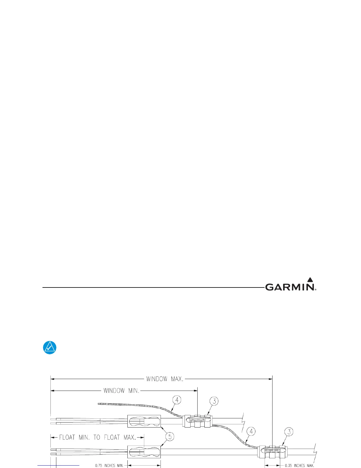
A.3 Shield Termination Technique - Method A.2 (Daisy Chain)
In rare situations where more braids need to be terminated for a connector than three per ring terminal it is
allowable to daisy chain a maximum of two shields together before coming to the ring terminal
(Figure A-4). All other restrictions and instructions for the shield termination technique set forth for
Method A.1 are still applicable.
The maximum length of the combined braids should be approximately 4 inches.
Figure A-4 Method A.2 (Daisy Chain) for Shield Termination
A.4 Shield Termination – Method B.1 (Quick Term)
If desired, the drain wire termination (item 3) and the floating shield termination (item 5) can be effectively
combined into a “Quick Term”. This method eliminates the float in the cable insulation and moves the
placement of the window which was described by the dimensions “Window Min” and “Window Max”
from Method A. This technique is depicted in Figure A-5
.
The original purpose for separating the shield drain termination (item 3) from the float
termination (item 5) in Method A was to allow for a variety of lengths for the drain wires
so that the shield drain terminations (item 3) would not all “bunch up” in the harness and
to eliminate loops in the drain wires. If Method B is chosen, as described in this section,
care must be taken to insure that all drain shield terminations can still be inspected. With
connectors which require a large number of shield terminations it may be best to use
Method A. This will allow the drain shield terminations (item 3) a larger area to be
dispersed across.
Using this method, the instructions from Section A.2
(Method A) are followed except that:
1. Step 2 is eliminated
2. Steps 3 and 4 are replaced by the following:
At the end of the shielded cable (item 2), strip “Quick Term Min” to “Quick Term Max”
(Table A-3) length of the jacket to expose the shield. Next trim the shield so that at most 0.35
inches remains extending beyond the insulating jacket. Fold this remaining shield back over the
jacket.

 Loading...


