190-01553-00 GTR 200 Installation Manual
Rev. B Page 3-13
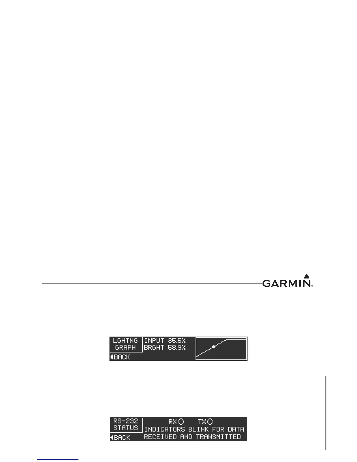
The Lighting Graph page Figure 3-10 graphically displays the input (voltage or percentage of lighting
sensor) and brightness in real time. Brightness level is displayed as the vertical (Y) axis, and input level is
displayed as the horizontal (X) axis. The graph changes according to the backlight control settings, and the
lighting source input level.
Figure 3-10 Lighting Graph
3.6.4.7 RS-232 Status Page
The RS-232 Status page (Figure 3-11) allows the installer to verify if RS-232 data is being received or
transmitted. The indicators next to both ‘RX’ and ‘TX’ will blink if data is being transmitted or received.
The RS-232 Status page is an information only page, there are no user-selectable settings.
Figure 3-11 RS-232 Status Page

 Loading...


