GTR 200 Installation Manual 190-01553-00
Page 3-18 Rev. B
3.6.6 Unit Ground Checks (Normal Mode)
3.6.6.1 TX Interlock Checkout
Connect pins 4 and 5 per Appendix D
.
3.6.6.2 Antenna Check
If desired, the antenna VSWR can be checked using an inline wattmeter in the antenna coaxial using
frequencies near both ends of the band. The VSWR should be less than 2:1. A VSWR of 2:1 will cause a
drop in output power of approximately 12%.
3.6.6.3 Receiver/Transmitter Check
Tune the unit to a local VHF frequency and verify the receiver output produces a clear and understandable
audio output. Verify the transmitter functions properly by contacting another station and getting a report
of reliable communications.
3.6.6.4 RS-232 Serial Interface Checks
The interfaces to RS-232 equipment such as the G3X sources should be checked as follows:
1. Operate the connected serial remote tune source and the GTR 200 in normal mode.
2. Ensure that the remote source is able to display data from the GTR 200.
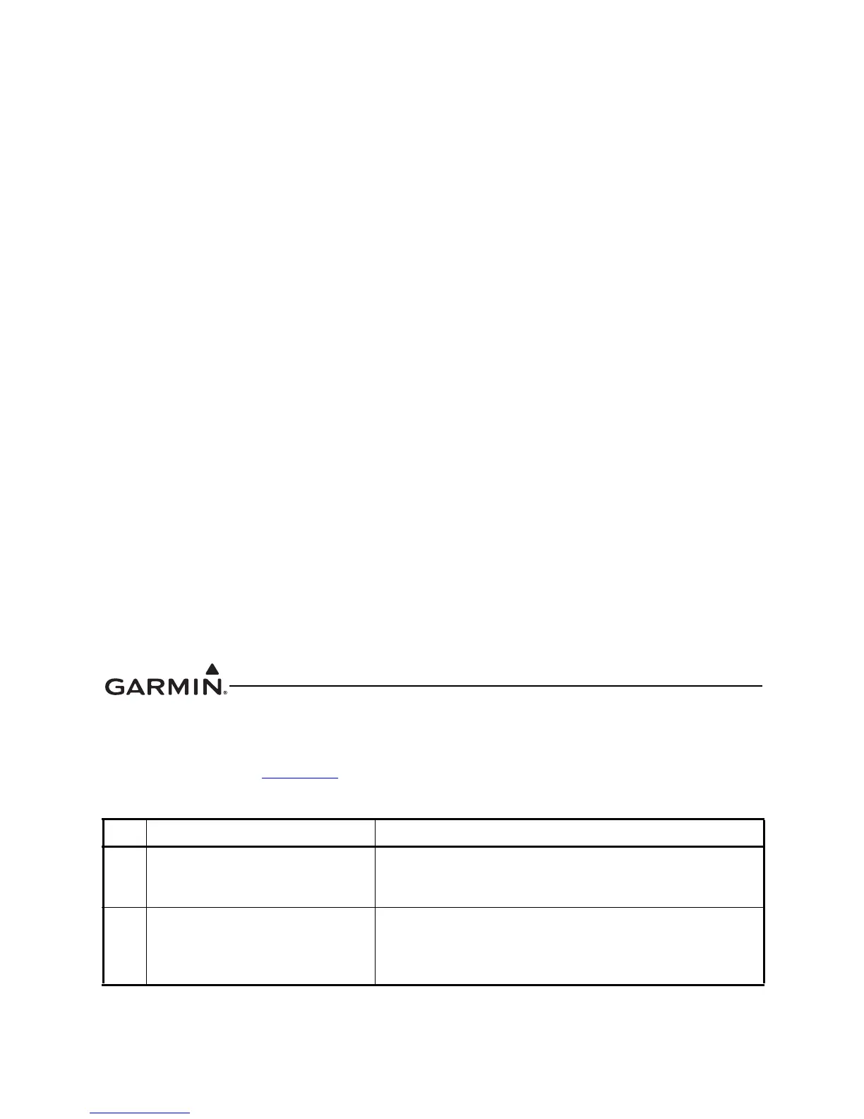
Table 3-11 TX Interlock Connections
Pin Pin Name Description
4 TX INTERLOCK OUT
Active low output that indicates the GTR 200 is transmitting.
This output is normally connected to the TX INTERLOCK IN
of other COM radios installed in the aircraft.
5 TX INTERLOCK IN
Active Low Input that ‘desenses’ (protects) the GTR 200
receiver when another communications radio is
transmitting. This input comes from another communication
radio's interlock output or MIC KEY line.

 Loading...


