GTR 200 Installation Manual 190-01553-00
Page 4-2 Rev. B
4.2 Power
Pins 1 & 20 supply power to the GTR 200. Refer to drawings in Appendix D for power and ground wire
gauges.
4.3 Lighting Bus
The lighting bus is configurable for either 14 or 28 Vdc input (Section 3.6.4.6). This pin is an input that
uses an external reference voltage to control the brightness of the display and backlight (it is not used to
power the lighting). The input impedance is approximately 163 kΩ.
Connecting the lighting bus to an incorrect pin can cause damage to the unit that will
require return to the factory for repair. Make sure that the lighting bus is connected to the
correct pin and does not short to any adjacent pins prior to applying power to the unit.
29 RECEIVER AUDIO LO --
30 COPILOT HS LO --
31 AUX 1 LO --
32 AUX MONO IN 1 In
33 PILOT HS LO --
34 COPILOT MIC LO --
35 PILOT PTT* In
36 PILOT MIC LO --
37 MUSIC LO In
*Indicates Active Low
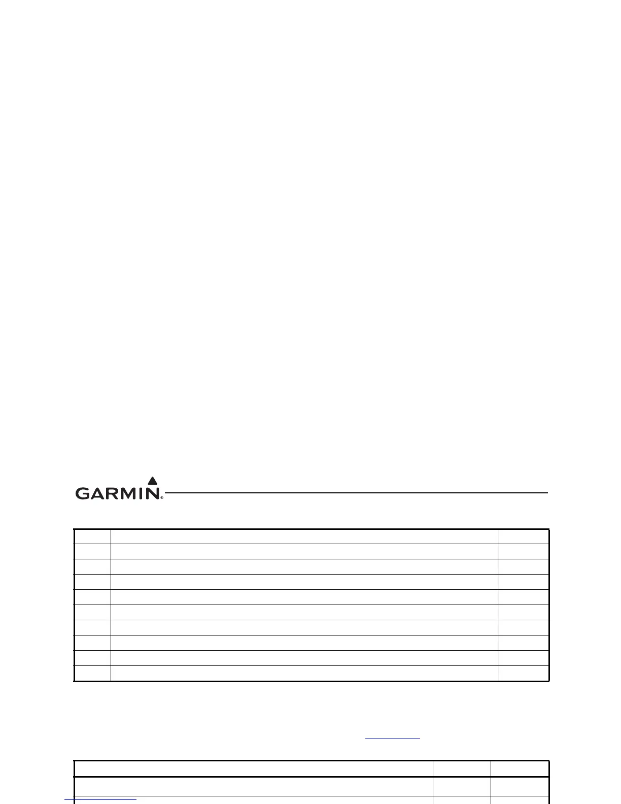
Pin Name Pin I/O
AIRCRAFT POWER 1 In
AIRCRAFT GROUND 20 --
Pin Name Pin I/O
LIGHTING BUS IN 3 In
Table 4-1 J2001 Connector
Pin Pin Name I/O

 Loading...


