6-24 D30 LINE DISTANCE PROTECTION SYSTEM – INSTRUCTION MANUAL
RECORDS CHAPTER 6: ACTUAL VALUES
6
The latest 15 fault reports can be stored. The most recent fault location calculation (when applicable) is displayed in this
menu, along with the date and time stamp of the event which triggered the calculation. See the
SETTINGS PRODUCT
SETUP FAULT REPORTS
menu for assigning the source and trigger for fault calculations. See the COMMANDS CLEAR
RECORDS
menu for manual clearing of the fault reports and to the SETTINGS PRODUCT SETUP CLEAR RELAY RECORDS
menu for automated clearing of the fault reports.
The
FAULT 1 LOOP RESISTANCE and REACTANCE are expressed in secondary ohms, which are calculated as per the following
equation.
Z
loop
= V
loop
/ I
loop
Eq. 6-5
The table defines the loop voltage and current.
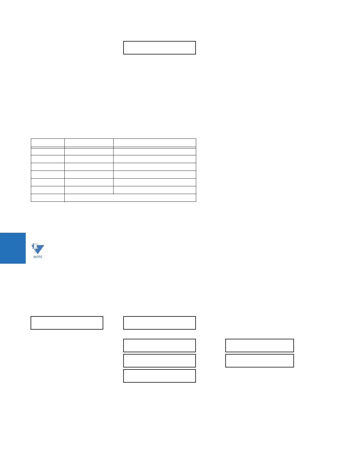
Table 6-3: Quantities used to calculate fault loop impedances
Where VA, VB, VC are phase voltage phasors in secondary volts; IA, IB, IC are current phasors in secondary amps, I0 is the
zero sequence current phasors in secondary amps; and IG is the ground current from the parallel line scaled to the source
phase CT in secondary amps. Z0/Z1 is the zero sequence impedance to positive sequence impedance ratio, and Z0M/Z1 is
mutual zero sequence impedance to positive sequence impedance ratio.
6.5.2 Event records
6.5.2.1 Enhanced and standard front panels
ACTUAL VALUES RECORDS EVENT RECORDS
FAULT 1 LOOP
REACT: 0.00 Ohms
Range: -327.67 to 327.67 Ohms
Fault type V
loop
I
loop
AG VA IA + (Z0/Z1-1)*I0 + Z0M/Z1*IG/3
BG VB IB + (Z0/Z1-1)*I0 + Z0M/Z1*IG/3
CG VC IC + (Z0/Z1-1)*I0 + Z0M/Z1*IG/3
AB, ABG VA – VB IA - IB
BC, BCG VB – VC IB - IC
CA, CAG VC – VA IC - IA
ABC Average of AB, BC, CA loop impedances
VTs of the FAULT REPORT 1 SOURCE must be connected in Wye or VT SUBSTITUTION must be set correctly for the Delta
connected VT to display the loop impedance and fault resistance for single phase-to-ground faults.
For the application of partially parallel circuits and in the case of single phase-to-ground faults, the reported fault
resistance and fault loop impedance may not be accurate even the compensation method is applied.
EVENT RECORDS
EVENT: XXX
XXX
Date and time stamps
EVENT: 3
POWER ON
EVENT 3
DATE: 2000/07/14
EVENT: 2
POWER OFF
EVENT 3
TIME: 14:53:00.03405
EVENT: 1
EVENTS CLEARED
 Loading...


