3-16 D30 LINE DISTANCE PROTECTION SYSTEM – INSTRUCTION MANUAL
WIRING CHAPTER 3: INSTALLATION
3
For high-reliability systems, the D30 has a redundant option in which two D30 power supplies are placed in parallel on the
bus. If one of the power supplies becomes faulted, the second power supply assumes the full load of the relay without any
interruptions. Each power supply has a green LED on the front of the module to indicate that it is functional. The critical fail
relay of the module also indicates a faulted power supply.
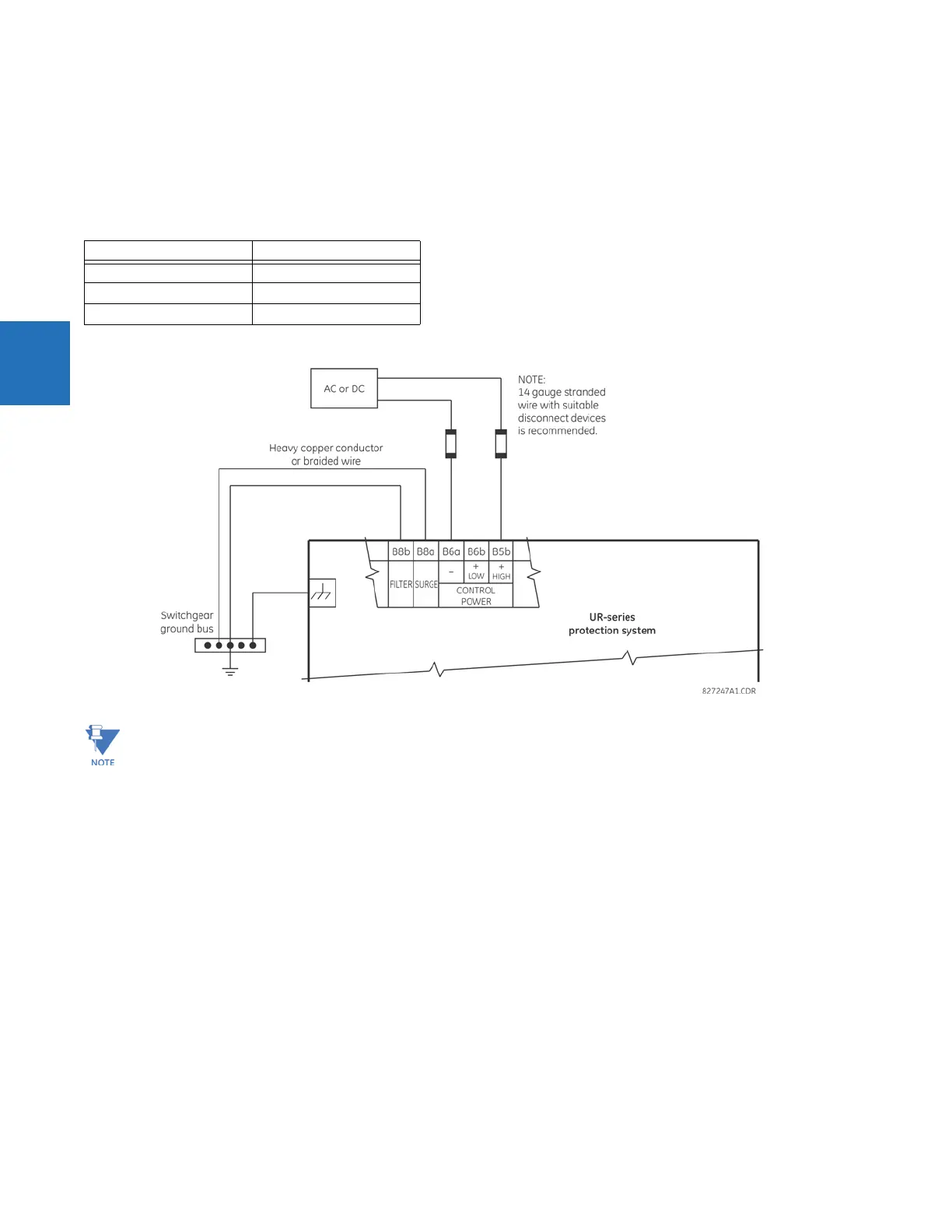
An LED on the front of the control power module shows the status of the power supply, as outlined in the table.
Table 3-2: Power supply LED on module
Figure 3-15: Control power connection
When using an SH power supply module, after disconnecting power and powering up again, some measured values
displayed can change from that last displayed. This is because there is not enough time for the compact flash to store
data. Upon power up the last stored value displays.
3.3.4 CT/VT modules
The CT and VT inputs are analog current transformer and voltage transformer signals used to monitor AC power lines. The
UR-series relays support 1 A and 5 A CTs.
A CT/VT module can have current or voltage inputs on channels 1 through 4 inclusive, or channels 5 through 8 inclusive.
Channels 1 and 5 are intended for connection to phase A, and are labelled as such in the relay. Likewise, channels 2 and 6
are intended for connection to phase B, and channels 3 and 7 are intended for connection to phase C.
Channels 4 and 8 are intended for connection to a single-phase source. For voltage inputs, these channels are labelled as
auxiliary voltage (VX). For current inputs, these channels are intended for connection to a CT between system neutral and
ground, and are labelled as ground current (IG).
LED indication Power supply
Continuous on OK
On/off cycling Failure
Off Failure or no power
When using a D30 with a HardFiber system, before powering off the D30, save data in the compact flash memory
using Commands > Relay Maintenance > Save Non-Volatile Data. When not saved or the relay loses power, up to
the last two minutes of data is not saved to the compact flash memory.
 Loading...


